
Aerosol laser radar system based on CCD lateral detection

A technology of laser radar and aerosol, which is applied in the direction of radio wave measurement system, measurement device, ICT adaptation, etc., can solve the problems of high-power pulse laser, optical receiving telescope expensive, spatial resolution reduction, and inability to measure, so as to avoid data Dealing with difficulties, increasing spatial resolution, and avoiding the effect of reducing accuracy

Pending Publication Date: 2020-10-13
NANJING XIAOZHUANG UNIV
View PDF0 Cites 3 Cited by
  • Summary
  • Abstract
  • Description
  • Claims
  • Application Information

AI Technical Summary

Problems solved by technology

The characteristic of meter scattering lidar detection is that the detection height is high, but high-power pulse lasers and optical receiving telescopes are relatively expensive, and the maintenance and use of many precision optical components require professional operation; the sun photometer uses the radiation intensity of different spectral bands of sunlight to reflect The aerosol coefficient is calculated by calculation, but its disadvantage is that it must rely on the sun, so it cannot be measured at night; CCD lateral detection lidar uses a single lens and CCD as the main receiving device to detect atmospheric aerosols, and usually uses a wide-angle lens to improve detection Altitude range, but at the same time will reduce the spatial resolution

Method used


Image

  • Aerosol laser radar system based on CCD lateral detection
  • Aerosol laser radar system based on CCD lateral detection
  • Aerosol laser radar system based on CCD lateral detection

Examples


Embodiment Construction

[0019] The technical solutions of the present invention will be further elaborated below in conjunction with the accompanying drawings and specific embodiments.

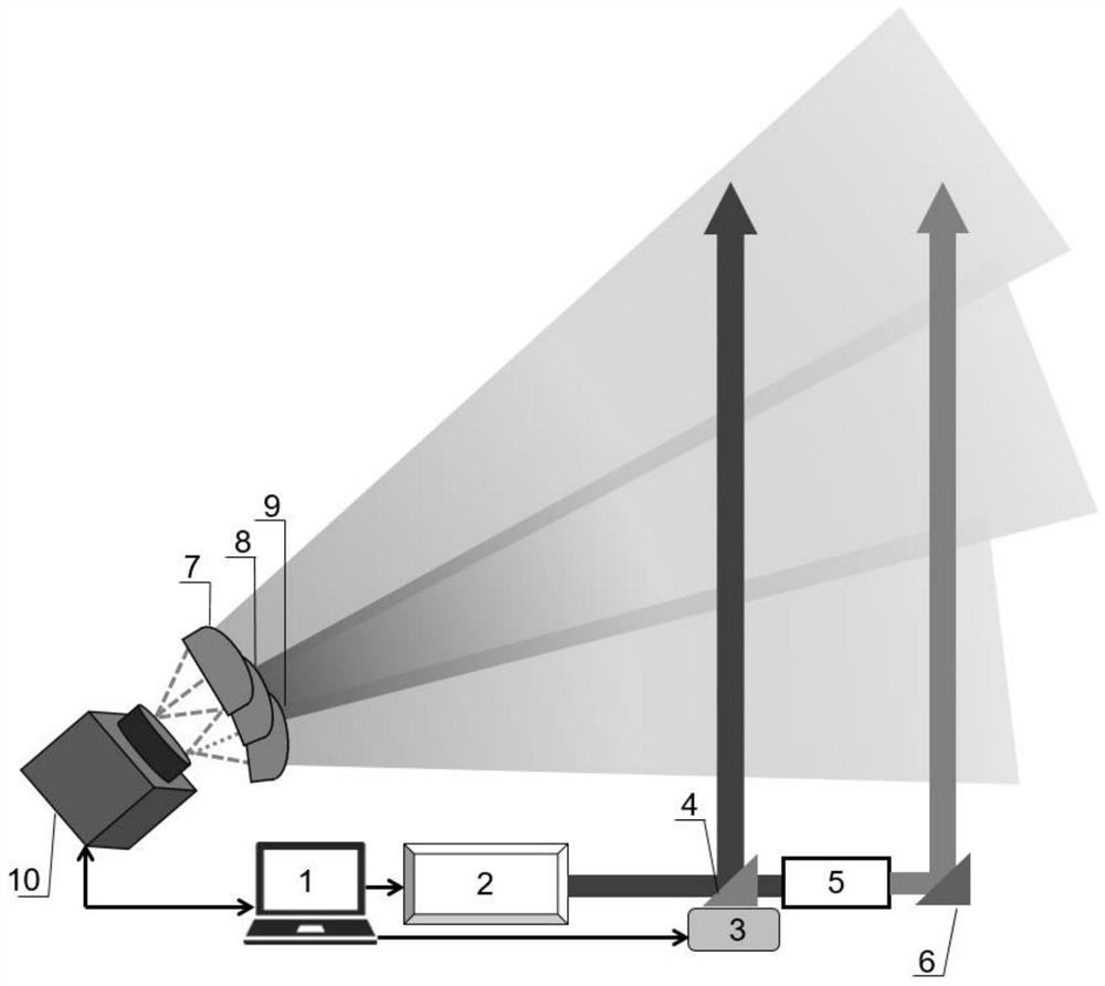
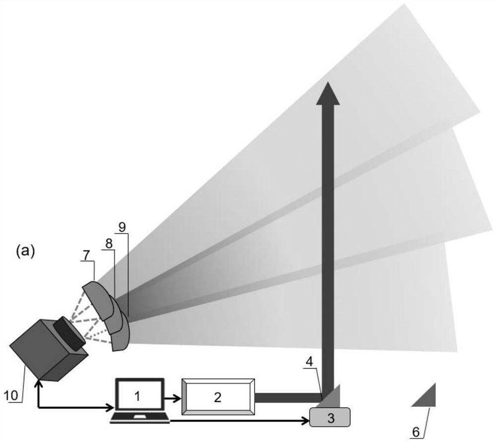
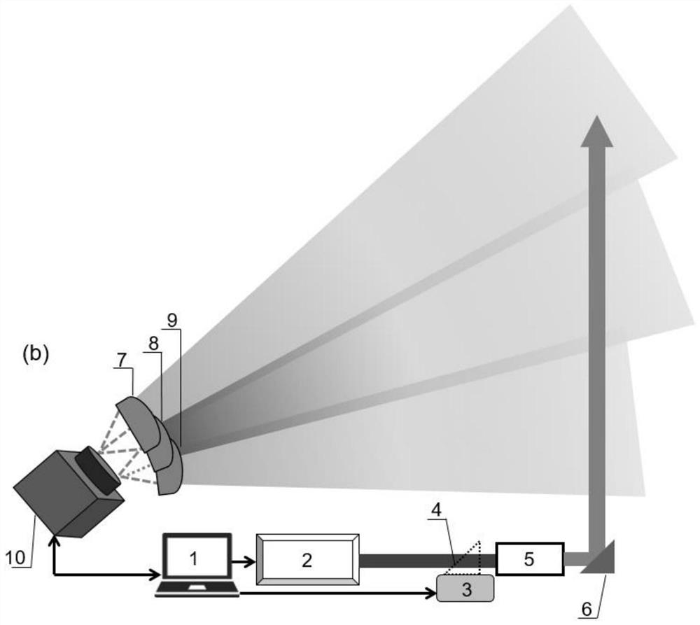
[0020] Such as Figure 1-8 Shown, the present invention is based on the aerosol lidar system of CCD lateral detection, comprises CCD10 and three cylinder mirrors (7,8,9) that place side by side along horizontal direction, three cylinder mirrors (7,8,9 ) corresponding to the axis passing through its focus and the angle between the horizontal plane increases or decreases successively (angle a is greater than angle b greater than angle c), and the focal lines of the three cylindrical mirrors (7, 8, 9) are located on the CCD detection surface at the same time 10; CCD10 and three cylindrical mirrors (7,8,9) are respectively fixed on the corresponding angle adjustment mechanism 11. The system of the present invention first adjusts the angles of the light-gathering surfaces of the three cylindrical mirrors (7, 8, 9) relati...


PUM


Abstract

The invention discloses an aerosol laser radar system based on CCD lateral detection. The aerosol laser radar system comprises a CCD and at least two cylindrical mirrors which are arranged side by side, wherein included angles between axes of the plurality of cylindrical mirrors correspondingly penetrating through focuses of the cylindrical mirrors and a horizontal plane are sequentially increasedor decreased progressively, and focal lines of the cylindrical mirrors are simultaneously positioned on a CCD detection surface; and the CCD and the plurality of cylindrical mirrors are respectivelyfixed on angle adjusting mechanisms corresponding to the CCD and the cylindrical mirrors. According to the laser radar detection system, the plurality of cylindrical mirrors which are arranged side byside at different angles are adopted to receive atmospheric aerosol information of different height sections at the same time, the plurality of cylindrical mirrors are used for replacing a traditional single lens, and the CCD can detect a plurality of side-by-side light beams representing a plurality of height sections, so that the spatial resolution of detection is improved on the premise that the detection height range is ensured, and meanwhile, the precision reduction of a bottom layer and a high layer due to fisheye lens distortion is avoided.

Description

technical field [0001] The invention relates to an aerosol laser radar detection system, in particular to an aerosol laser radar system based on CCD lateral detection. Background technique [0002] Atmospheric aerosols are small solid or liquid particles suspended in the air, mainly including dust, smoke, pollen, volcanic ash, etc. According to particle size, it can be divided into total suspended particulate matter (TSP), inhalable particulate matter with a diameter of less than 10 μm (PM10) and fine particulate matter with a diameter of less than 2.5 μm (PM2.5). Atmospheric aerosols not only interfere with the sun's radiation to the ground and affect the climate system, but also many harmful substances in aerosols can affect people's lives and health. The detection and research of atmospheric aerosols has become one of the important hotspots in the fields of atmospheric science and environmental science (Shi Guangyu et al., Radiation and Climate Effects of Atmospheric Aer...

Claims


Application Information

Patent Timeline
IPC IPC(8): G01S17/95G01S7/481
CPCG01S17/95G01S7/4816G01S7/481Y02A90/10
Inventor 夏媛张磊李亚娟李冲
Owner NANJING XIAOZHUANG UNIV
Learn More