A cable with high compression resistance
A cable and functional technology, applied in the field of cables with high compression resistance, can solve problems such as cable short circuit, and achieve the effect of easy laying
- Summary
- Abstract
- Description
- Claims
- Application Information
AI Technical Summary
Problems solved by technology
Method used
Image

Examples
Embodiment
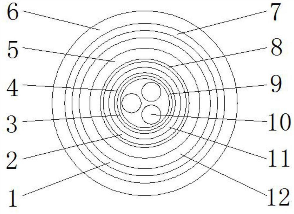
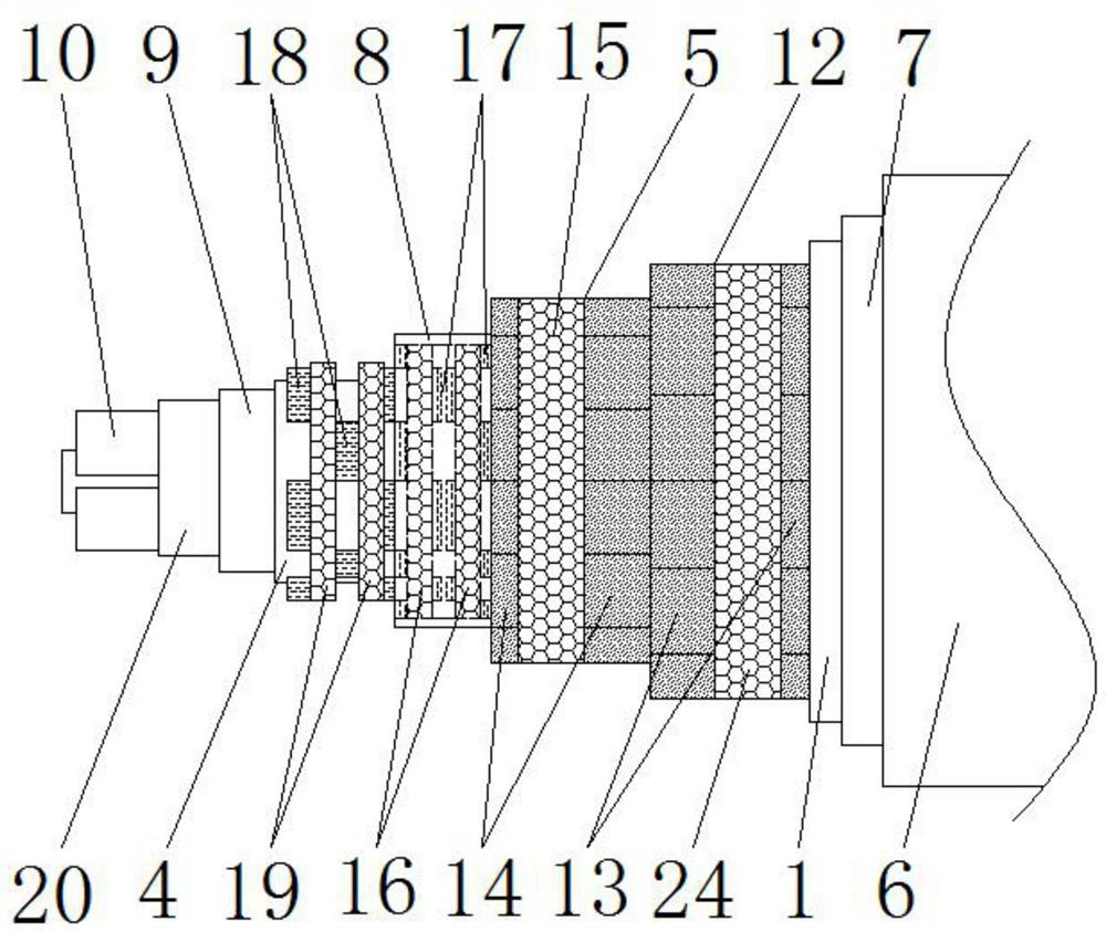
[0028] Such as figure 1 and figure 2 A cable with high compressive resistance is shown, including a cable core body 3, a functional layer 1, an armor layer 7 and an outer sheath 6 arranged sequentially from the inside to the outside, as shown in Figure 5 As shown, the cable core body 3 includes a wire core 10, an inner protective layer 9 coated on the surface side of the cable core body 3, and a filler material 21 filled around the wire core 10; Flame retardant, waterproof and other advantages of at least one material, so that the cable has the corresponding performance; the armor layer 7 can adopt non-magnetic stainless steel belt interlocking armor structure, the metal armor layer set in this way has excellent Mechanical, compressive, antimagnetic, fireproof, easy to bend and other performances, and also has anti-theft, anti-insect bites, etc., which can enhance the related performance of the cable; the outer sheath 6 can be made of low-smoke halogen-free rubber, and its ...
Embodiment 2
[0033] The difference between this embodiment and embodiment 1 is:
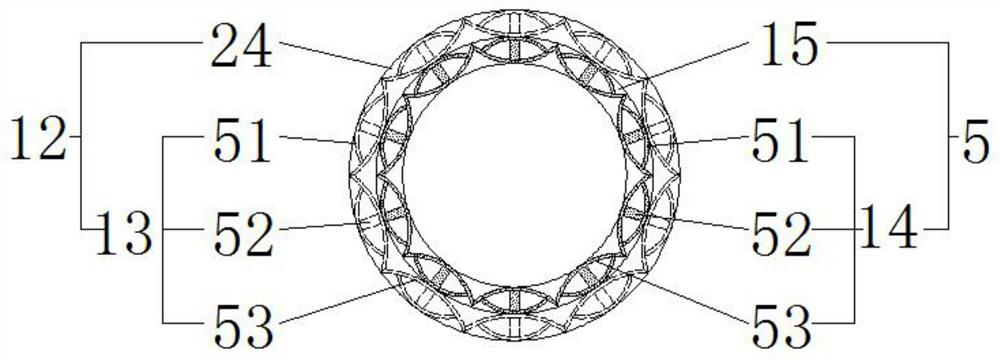
[0034] In this example, if figure 1 and Figure 4 As shown, the inside of the second compression layer 5 is provided with a third compression layer 2 and a fourth compression layer 11 located inside the third compression layer 2, and the outside of the third compression layer 2 is provided with The first elastic layer 8, the inner side of the fourth anti-pressure layer 11 is provided with the second elastic layer 4, the first elastic layer 8 and the second elastic layer 4 can be made of rubber, the fourth anti-pressure layer 11 includes inner anti-pressure blocks 18 fixedly arranged at equal intervals along the outer peripheral side of the second elastic layer 4, and the third anti-pressure layer 2 includes outer anti-pressure blocks 17 fixedly arranged at equal intervals along the inner peripheral side of the first elastic layer 8, Both the outer anti-compression block 17 and the inner anti-compression blo...
Embodiment 3
[0038] The difference between this embodiment and embodiment 2 is:
[0039] In this example, if Figure 5 and Figure 6 As shown, the cable core body 3 is provided with a protective bracket 20 located inside the inner protective layer 9. The protective bracket 20 can be made of copper material. The small round bracket 22 on the outside and the large round bracket 23 attached to the inside of the inner protective layer 9, the side of the small round bracket 22 facing away from the center of the cable section is fixed together with the large round bracket 23, and every adjacent two small round brackets The round brackets 22 all interfere with each other. Small circle support 22 and large circle support 23 are all circular, have anti-compression effect, and by each small circle support 22 contradict each other and small circle support 22 and big circle support 23 are fixedly connected, make between each small circle support 22 and Both the small round bracket 22 and the big ro...
PUM
 Abstract
Description
Claims
Application Information
 - R&D
- Intellectual Property
- Life Sciences
- Materials
- Tech Scout
- Unparalleled Data Quality
- Higher Quality Content
- 60% Fewer Hallucinations
Browse by: Latest US Patents, China's latest patents, Technical Efficacy Thesaurus, Application Domain, Technology Topic, Popular Technical Reports.
© 2025 PatSnap. All rights reserved.Legal|Privacy policy|Modern Slavery Act Transparency Statement|Sitemap|About US| Contact US: help@patsnap.com