Valve stent and artificial heart valve including valve stent

A valve and stent sleeve technology, applied in the field of medical devices, can solve the problems of easily damaged sheath, large end recovery resistance, and affecting the valve, so as to reduce the risk of damage to the sheath, reduce loading resistance, and improve the overall effect

Pending Publication Date: 2020-10-16
SHANGHAI TRULIVE MEDTECH CO LTD +1
View PDF0 Cites 5 Cited by
  • Summary
  • Abstract
  • Description
  • Claims
  • Application Information

AI Technical Summary

Problems solved by technology

When loading, the end face of the outer stent will touch the end face of the sheath, and the two end faces will be in conflict, thus affecting the entry of the entire valve into the sheath. The loading resistance is large, and the outer stent is easy to damage the sheath, and there is a possibility that the sheath enters the two-layer stent The risk of mezzanine
During the implantation process, if it needs to be recovered and then released, the recovery resistance at this end is large, which will also affect the smooth progress of recovery

Method used


Image

  • Valve stent and artificial heart valve including valve stent
  • Valve stent and artificial heart valve including valve stent
  • Valve stent and artificial heart valve including valve stent

Examples


Embodiment 1

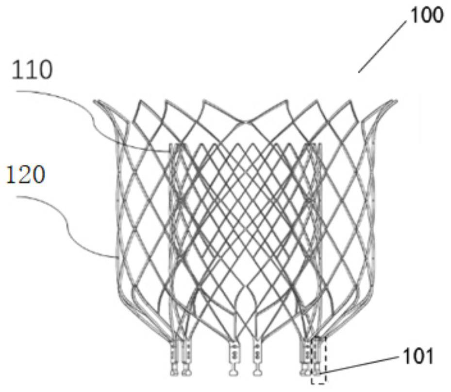
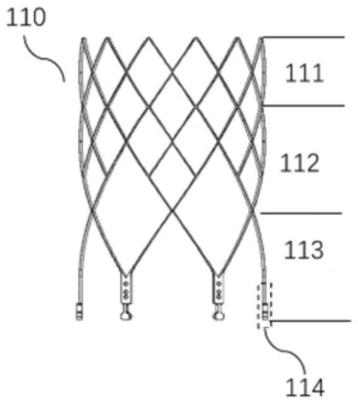
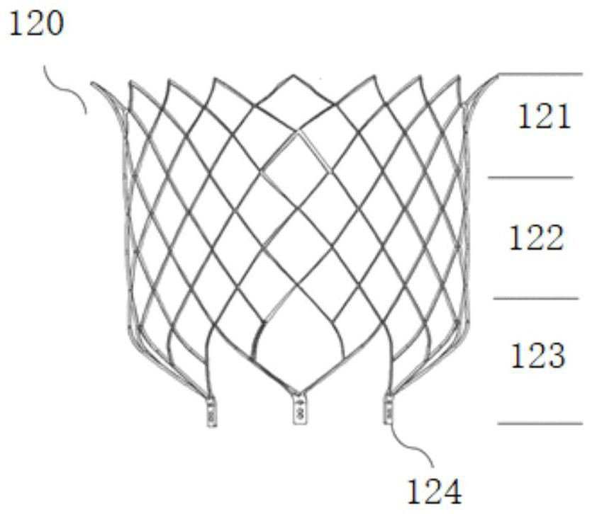
[0064] This embodiment provides a valve stent, including a stent assembly 100, see Figure 1-Figure 8 , wherein, the bracket assembly 100 includes two brackets, an inner bracket 110 and an outer bracket 120, the inner bracket 110 and the outer bracket 120 are nested inside and outside, the inner bracket 110 is sleeved inside, and the outer bracket 120 Set outside.

[0065] The stent assembly 100 is configured to have at least one sheath-in end set 101, and at least one sheath-in end set 101 includes a first sheath-in end 114 and a second sheath-in end 124, wherein the first sheath-in end 114 is located on the inner layer stent 110 , the second sheathing end 124 is located on the outer stent 120 , the first sheathing end 114 and the second sheathing end 124 extend towards the same direction, and the second sheathing end 124 is located outside the first sheathing end 114 .

[0066] In at least one sheath-in end group 101, the length of the first sheath-in end 114 is greater tha...

Embodiment 2

[0080] This embodiment provides a valve support, which is an improvement on the basis of Embodiment 1, wherein the outer contour of the protrusion 200 is arc-shaped.

[0081] Such as Figure 9 As shown, since the first end surface 201 of the protruding part 200 abuts against the end surface 1241 of the second sheathing end, the arc-shaped outer contour can reduce the friction between the end surface of the sheath and the inner wall of the sheath, further Reduced loading resistance.

Embodiment 3

[0083] This embodiment provides a valve stent, which is an improvement on the basis of Embodiment 1 or Embodiment 2, wherein the axial contact surfaces of the first sheath-in end 114 and the second sheath-in end 124 are configured For concave-convex matching connection.

[0084] see Figure 10 , the axial side of the second sheath-in end 124 protrudes outwards with a plurality of second protrusions, and a second recess is formed between two adjacent second protrusions; correspondingly, the axial side of the first sheath-in end 114 forms There are multiple first recesses, and a first protrusion is between two adjacent first recesses 116 . After the inner bracket 110 is connected to the outer bracket 120, the first protrusions are respectively located in a corresponding second recess, and the second protrusions are respectively located in a corresponding first recess, so that the first sheath-in end 114 and the second A concave-convex matching connection is formed between the ...


PUM


Abstract

The invention discloses a valve stent. The valve stent comprises a stent assembly, wherein the stent assembly comprises at least two stents of an inner layer stent and an outer layer stent, the innerlayer stent and the outer layer stent adopt an inside and outside nested structure, the stent assembly is configured to have one or more invagination end groups including first invagination ends and second invagination ends, and the second invagination ends are located outside the first invagination ends; in the invagination end groups, the length of each first invagination end is greater than that of the corresponding second invagination end; and the invagination end groups are provided with raised parts for preventing the invagination end groups from causing interference on loading of valveprosthesis. The invention also provides an artificial heart valve. According to the valve stent disclosed by the invention, the raised parts can prevent the second invagination ends of the outer layerstent from being in touch with ends of a sheath to influence loading, and loading resistance and the risk that the sheath enters an interlayer can be reduced.

Description

technical field [0001] The invention relates to the technical field of medical devices, in particular to a valve support and an artificial heart valve implanted in the heart. Background technique [0002] Heart valves are membrane-like structures that can open and close in the organs of humans or certain animals. Every human heart has four valves. The aortic valve connects the left ventricle to the aorta, the pulmonary valve connects the right ventricle to the pulmonary artery, the mitral valve connects the left atrium to the left ventricle, and the tricuspid valve connects the right atrium to the right ventricle. They all act as one-way valves, so that blood can only flow from one direction to the other and not back. [0003] Mitral regurgitation leads to myocardial remodeling, progressive ventricular enlargement, and eventually heart failure. Transcatheter Mitral Valve Replacement (TMVR) uses a catheter intervention method to compress the artificial valve to the deliver...

Claims


Application Information

Patent Timeline
Patent Type & Authority Applications(China)
IPC IPC(8): A61F2/24
CPCA61F2/2412A61F2/2418A61F2/2436
Inventor 不公告发明人
Owner SHANGHAI TRULIVE MEDTECH CO LTD
Why Eureka
Try Eureka