Soot blower continuous position monitoring system and method

A monitoring system and a soot blower technology, which are applied in the combustion method, control combustion, safety device of the combustion chamber, etc., can solve problems such as damaged equipment, hidden dangers, and inability to monitor, achieve wide application prospects, simple structure, and reduce discovery long time effect

Active Publication Date: 2020-10-16
国家能源(山东)工程技术有限公司
View PDF13 Cites 0 Cited by
  • Summary
  • Abstract
  • Description
  • Claims
  • Application Information

AI Technical Summary

Problems solved by technology

[0014] For the above-mentioned long sootblowers in the prior art, both front and rear travel switches are used to determine the position of the sootblower. Potential safety hazards and defects of damaged equipment, the present invention provides a continuous position monitoring system and method for sootblowers to solve the above technical problems

Method used


Image

  • Soot blower continuous position monitoring system and method
  • Soot blower continuous position monitoring system and method
  • Soot blower continuous position monitoring system and method

Examples


Embodiment 1

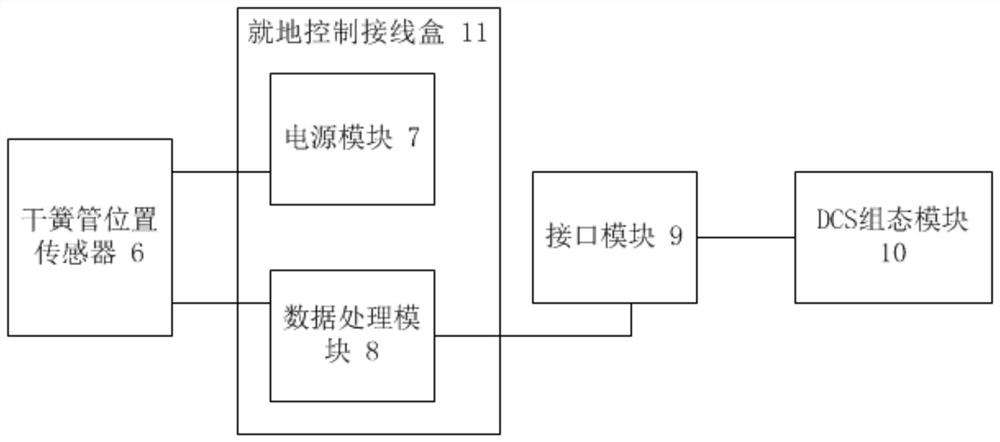
[0088] Such as figure 1 and figure 2 As shown, the present invention provides a continuous position monitoring system for a sootblower, including a reed switch position sensor 6, a local control junction box 11, an interface module 9 and a DCS configuration module 10;

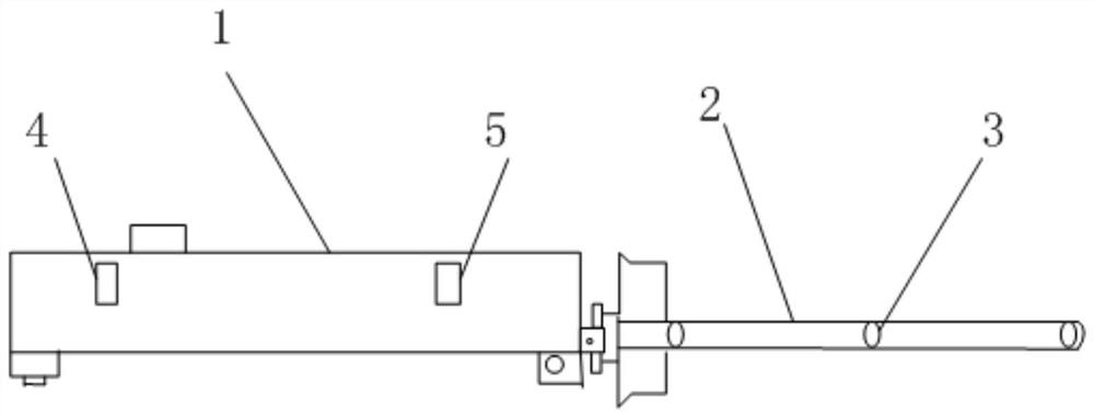
[0089] The sootblower adopts a long telescopic sootblower, including a soot blower and a sports car; the sports car includes a motor and a gear box 1;

[0090] The soot blowing gun includes a nozzle 2, which is provided with a nozzle 3; the nozzle 2 runs through the gear box 1, and the motor drives the nozzle 2 to move forward or backward;

[0091] The gear box 1 is provided with a retractable travel switch 4 and a forward travel switch 5. The retractable travel switch 4 is used to detect whether the print head 2 has reached the maximum backward position, and the forward travel switch 5 is used to detect whether the print head 2 has reached the maximum forward position. Location;

[0092] The reed switch po...

Embodiment 2

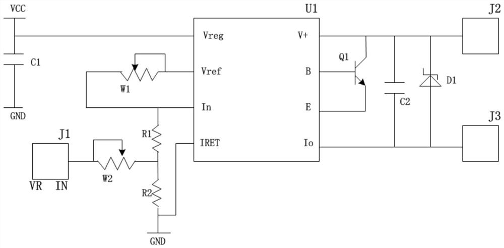
[0104] Such as image 3 As shown, the difference from Embodiment 1 is that the data processing module 8 includes a current loop chip U1, and the current loop chip U1 includes a calibration voltage terminal Vreg, a reference voltage terminal Vref, an input terminal In, a current return terminal IRET, a voltage terminal V+, a base Pole connection terminal B, emitter connection terminal E and current output terminal Io;

[0105] The calibration voltage terminal Vreg is connected to the first capacitor C1 and the power supply terminal VCC, and the other end of the first capacitor C1 is grounded;

[0106] The reference voltage terminal Vreg is connected with a first sliding resistor W1;

[0107] The input terminal In is connected to the first resistor R1, and is also connected to the other end of the sliding resistor W1; the other end of the first resistor R1 is connected to the second resistor R2 and the second sliding resistor W2, and the other end of the second resistor R2 is c...

Embodiment 3

[0116] Such as Figure 4 As shown, in above-mentioned embodiment 1, the quantity of described soot blower is 16, and the quantity of reed switch position sensor 6 and data processing module 8 is equal to the quantity of soot blower, is 16;

[0117] The DCS cards of the interface module 8 are all connected to the sixteen data processing modules, and the sixteen data processing modules 8 are respectively connected to the corresponding reed switch position sensors 6;

[0118] The interface module 9 includes a gating unit 9.1, an analog-to-digital conversion unit 9.2, a photoelectric isolation unit 9.3 and a control unit 9.4;

[0119] The gating unit 9.1 is connected to the analog-to-digital conversion unit 9.2, the analog-to-digital conversion unit 9.2 is connected to the photoelectric isolation unit 9.3, and the photoelectric isolation unit 9.3 is connected to the control unit 9.4;

[0120] The control unit 9.4 is connected with the DCS configuration module 10;

[0121] The ga...


PUM


Abstract

The invention provides a soot blower continuous position monitoring system and method. The system comprises a reed switch position sensor, a local control junction box, an interface module and a DCS configuration module. The soot blower is a long telescopic soot blower and comprises a soot blowing gun and a running car, wherein the running car comprises a motor and a gear box; the soot blowing guncomprises a spray head, and a nozzle is arranged on the spray head, and the spray head penetrates through the gear box and is driven by the motor to advance or retreat; a retreat-in-place travel switch and a forward-in-place travel switch are arranged in the gear box, the retreat-in-place travel switch is used for detecting whether the spray head reaches the maximum retreat position or not, and the forward-in-place travel switch is used for detecting whether the spray head reaches the maximum forward position or not; the reed switch position sensor is arranged at the spray head of the soot blowing gun; a power supply module and a data processing module are arranged in the local control junction box; and the reed switch position sensor is connected with the power supply module and the dataprocessing module, the data processing module is connected with the interface module, and the interface module is connected with the DCS configuration module.

Description

technical field [0001] The invention belongs to the technical field of position measurement of a steam soot blower in a coal-fired power plant, and in particular relates to a continuous position monitoring system and method for a soot blower. Background technique [0002] Coal-fired power plant boilers run for a long time, and the heating surface will produce ash and coke, which will deteriorate the heat transfer. For the tail flue, due to the long-term accumulation of combustibles, there will be vicious accidents of re-combustion. Therefore, after the boiler runs for a period of time After that, it is necessary to carry out soot blowing work on the heating surface to clean the heating surface. In particular, the sootblower at the position of the flue such as the superheater has a length of more than 10 meters, and due to the high pressure of coal combustion in recent years, the coal combustion indicators of major power plants have declined, resulting in frequent work of the...

Claims


Application Information

Patent Timeline
IPC IPC(8): F23J3/00F23M11/00F23N5/24
CPCF23J3/00F23M11/00F23N5/242
Inventor 王庆想刘卫东赵建新李军韩怀月宋益纯何刚赵培山
Owner 国家能源(山东)工程技术有限公司
Why Eureka
Try Eureka