
Intelligent control method and control system for heat conducting oil furnace

A heat-conducting oil furnace, intelligent control technology, applied in heat storage heaters, fluid heaters, lighting and heating equipment, etc., can solve the problems of untimely operation, low degree of automation, and low work efficiency, and meet the needs of external heat consumption effect of demand

Active Publication Date: 2020-10-16
FOSHAN SANSHUI YUSN DECORATION IND
View PDF6 Cites 0 Cited by
  • Summary
  • Abstract
  • Description
  • Claims
  • Application Information

AI Technical Summary

Problems solved by technology

However, in actual operation, technical personnel are basically manually operated to control the boiler system, not only to achieve the purpose of energy saving and emission reduction, to meet the national emission standards, but also to ensure that the temperature of the heat transfer oil meets the working temperature, but this method There are disadvantages such as untimely operation, large hysteresis, large fluctuation range, low degree of automation, and failure to ensure that the temperature of the heat transfer oil is within the working temperature range, resulting in low work efficiency

Method used


Image

  • Intelligent control method and control system for heat conducting oil furnace
  • Intelligent control method and control system for heat conducting oil furnace
  • Intelligent control method and control system for heat conducting oil furnace

Examples


Embodiment Construction

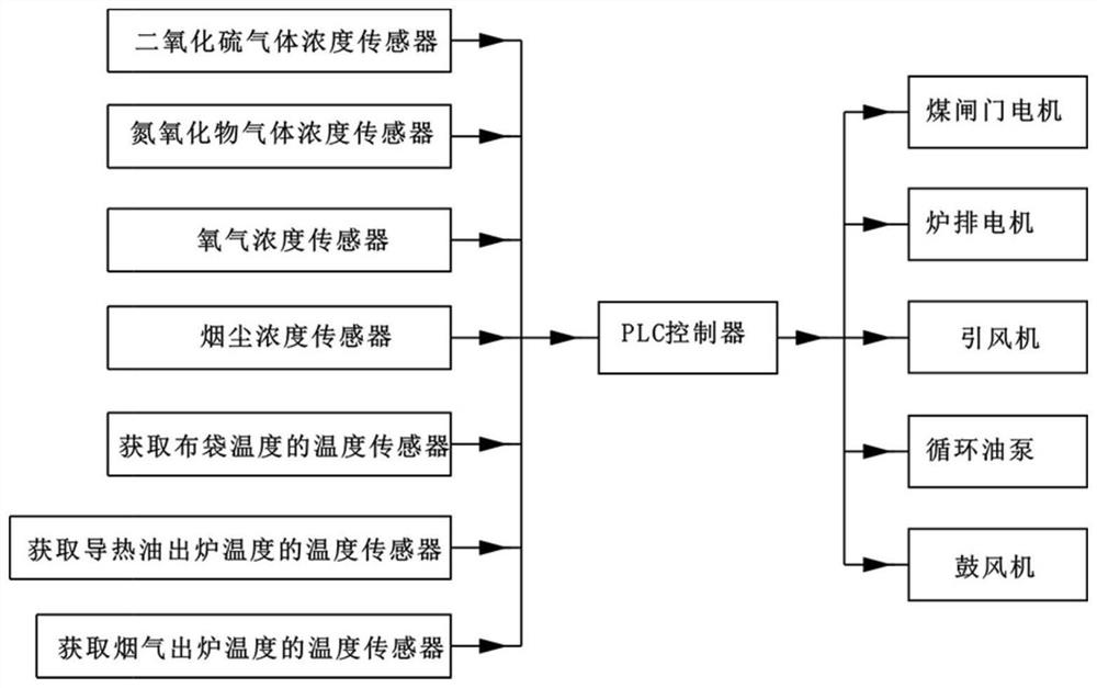
[0045] The present invention provides an intelligent control method and control system for a heat-conducting oil furnace. In order to make the purpose, technical solution and effect of the present invention clearer and clearer, the present invention will be further described in detail below with reference to the accompanying drawings and examples. It should be understood that the specific embodiments described here are only used to explain the present invention, not to limit the present invention.

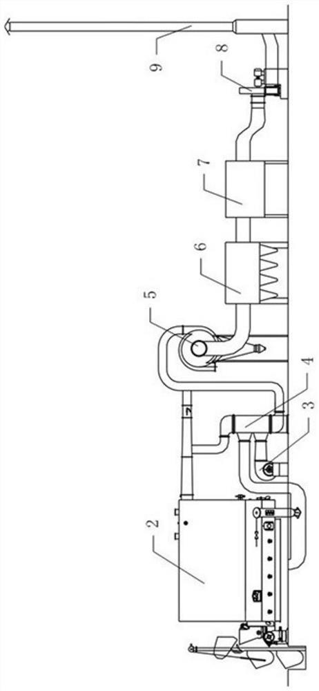
[0046] see figure 2, such as the heat-conducting oil furnace system disclosed in the utility model patent application number 201920364986.9, wherein the specific structure includes a biomass-fired heat-conducting oil furnace 2, a blower 3, an air preheater 4, a cyclone dust collector 5, and a pulse bag filter 6 , water curtain spray device 7, induced draft fan 8, chimney 9.

[0047] The flue gas outlet of the heat-conducting oil furnace 2 is respectively connected to the tube-sid...


PUM


Abstract

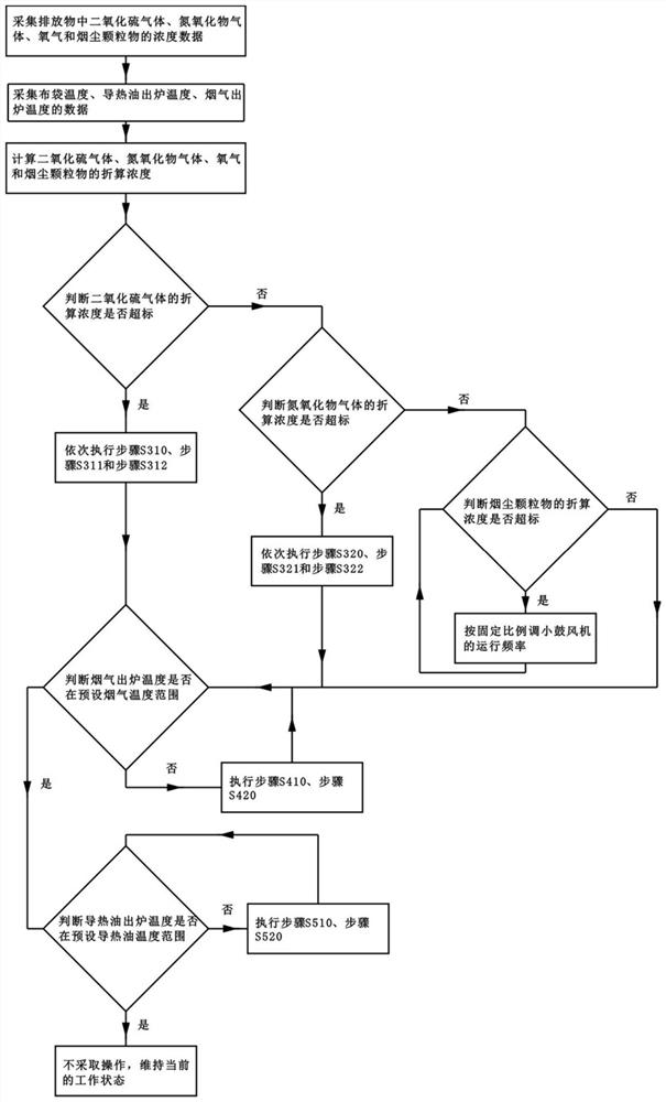
The invention provides an intelligent control method and control system for a heat conducting oil furnace. The method comprises the steps that concentrations of sulfur dioxide, nitrogen oxides, oxygenand soot particulate matter are collected and the converted concentrations of the sulfur dioxide, the nitrogen oxides, the oxygen and the soot particulate matter are calculated; the cloth bag temperature, the heat conducting oil out-of-furnace temperature and the flue gas out-of-furnace temperature are collected; whether the sulfur dioxide, the nitrogen oxides and the soot particulate matter exceed the standard or not, whether the flue gas out-of-furnace temperature is within the preset temperature range or not and whether the heat conducting oil out-of-furnace temperature is within the preset temperature range or not are judged successively; if the sulfur dioxide exceeds the standard, the air volumes of an air blower and an induced draft fan are increased in sequence, and the opening ofa coal gate is reduced; if the cloth bag temperature exceeds the set temperature, the air volumes of the air blower and the induced draft fan are reduced; if the nitrogen oxides exceed the standard, the air volumes of the air blower and the induced draft fan are reduced in sequence, and the opening of the coal gate is reduced; if the soot particulate matter exceeds the standard, the air volume ofthe air blower is reduced until the standard is reached; if the flue gas out-of-furnace temperature is not within the preset temperature range, a furnace bar motor is controlled to work; and if the heat conducting oil out-of-furnace temperature is not within the preset temperature range, a circulating oil pump is controlled to work.

Description

technical field [0001] The invention belongs to the technical field of heat-conducting oil furnace control, and in particular relates to an intelligent control method and control system for a heat-conducting oil furnace. Background technique [0002] Heat-conducting oil furnace (or heat-conducting oil boiler) is a new type of thermal energy equipment that uses coal, oil, and gas as fuel and heat-conducting oil as the circulating medium to provide heat. It has uniform heating, simple operation, safety and environmental protection, energy saving, and high temperature control accuracy. , low operating pressure and other advantages, so its application is very wide, including the wood industry. However, in actual operation, technical personnel are basically manually operated to control the boiler system, not only to achieve the purpose of energy saving and emission reduction, to meet the national emission standards, but also to ensure that the temperature of the heat transfer oil...

Claims


Application Information

Patent Timeline
Patent Type & Authority Applications(China)
IPC IPC(8): F24H7/00F24H9/20
CPCF24H7/007F24H9/20
Inventor 王志辉
Owner FOSHAN SANSHUI YUSN DECORATION IND
Learn More