Rotor forming mechanism and forming method thereof

A molding mechanism and molding method technology, applied in the direction of rotor, manufacturing stator/rotor body, stator, etc., can solve the problems of reducing the efficiency of aluminum die-casting of the rotor, affecting the conductivity of the self-rotating winding, and production accidents.

Pending Publication Date: 2020-10-20
江阴市海达电机冲片有限公司
View PDF0 Cites 1 Cited by
  • Summary
  • Abstract
  • Description
  • Claims
  • Application Information

AI Technical Summary

Problems solved by technology

[0004] 1. The traditional aluminum die-casting machine has a low degree of automation. After the rotor die-casting process is completed, the rotor needs to be taken out manually, and then the next rotor can be die-cast. It may burn the operator who takes the rotor and cause a production accident;
[0005] 2. The traditional process of injecting molten aluminum into the cavity is completed by the operator manually scooping the molten aluminum from the aluminum pool and pouring it into the cast aluminum cavity. The gas emitted by the liquid aluminum is harmful to the human body and will cause chronic Poisoning, and manual scooping of aluminum also increases labor costs and the risk of potential human accidents;
[0006] 3. The aluminum block contains a small amount of impurities. After the aluminum block is melted in the traditional aluminum pool, the impurities will float on the surface of the metal aluminum liquid. When the aluminum liquid is directly scooped up by a ladle, the impurities will be scooped at the same time, which will affect the rotation of the cast aluminum. The conductivity of the windings will affect the performance of the three asynchronous motors. At the same time, the traditional aluminum pool cannot use a spoon to scoop up the metal aluminum liquid during the melting process of the aluminum block. Only after the aluminum block is completely melted can the aluminum liquid be carried out. The process of scooping and subsequent aluminum casting seriously affects the continuity and production efficiency of the rotor manufacturing process

Method used


Image

  • Rotor forming mechanism and forming method thereof
  • Rotor forming mechanism and forming method thereof
  • Rotor forming mechanism and forming method thereof

Examples


Embodiment Construction

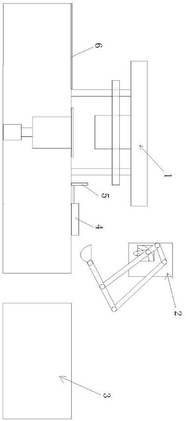
[0033] see Figure 1 to Figure 7 , a rotor forming mechanism and a forming method thereof related to the present invention, the method steps are:

[0034] Step 1: manually put the aluminum block into the right half pool 3.3 of the aluminum pool 3;

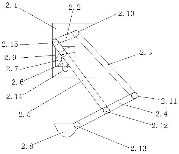
[0035] Step 2: The robotic arm 2 controls the scoop 2.8 to scoop the aluminum liquid in the left half pool 3.4 of the aluminum pool 3, and then pours the aluminum liquid into the lower half mold cavity 1.7;

[0036] Step 3: Manually place the rotor lamination directly above the cavity 1.7 of the lower half-mold;

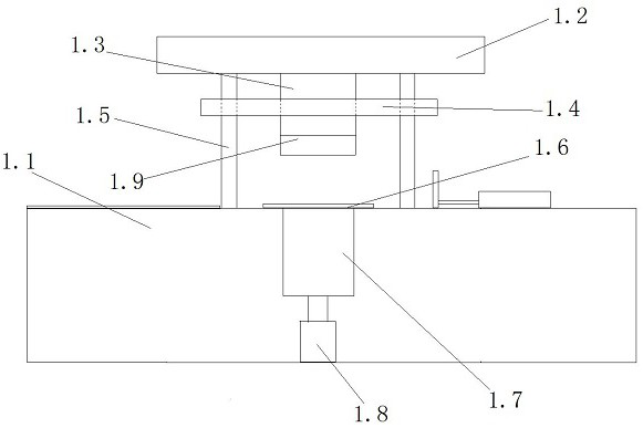
[0037] Step 4: The hydraulic cylinder pushes the hydraulic rod 1.3 downward, the hydraulic rod 1.3 drives the middle beam 1.4 to move downward along the column 1.5, and the upper half mold 1.9 presses down the rotor laminations until the rotor laminations are completely pressed into the lower half cavity Body 1.7, after staying for a period of time, the hydraulic cylinder pulls up the hydraulic rod 1.3 upward;

[0038]...


PUM


Abstract

The invention relates to a rotor forming mechanism and a forming method thereof. The rotor forming mechanism comprises a die-casting machine, a mechanical arm and an aluminum pool. The die-casting machine is provided with a lower half die cavity with an ejection air cylinder at the bottom, a rotor is subjected to die-casting through an upper half die, the rotor is ejected out of the cavity after aluminum casting, then the rotor is pushed to a conveying belt through a displacement air cylinder, and the conveying belt conveys the rotor to the next station. The mechanical arm can automatically scoop molten aluminum from the left half pool of the aluminum pool through the ingenious design of the transmission rod, the driven shaft, the driving shaft and the scoop, and then the molten aluminum is injected into the lower half die cavity. A partition plate is arranged on the aluminum pool and divides the aluminum pool into a left half pool and a right half pool, the bottom of the partition plate is higher than the upper bottom face of the tank body, and a circulation opening is formed between the bottom of the partition plate and the upper ground of the tank body. According to the rotor forming mechanism and the forming method thereof, the quality of a cast-aluminum rotor is improved, the production continuity and the automation degree are optimized, the production efficiency is improved, and meanwhile, the labor investment is reduced.

Description

technical field [0001] The invention relates to a rotor forming mechanism and a forming method thereof. Background technique [0002] The three-phase asynchronous motor is mainly composed of a stator and a rotor. The rotor part mainly has an iron core, a rotor winding and a rotating shaft. The rotor winding is injected into the rotor iron core slot by liquid aluminum, and the guide bars in the slot and the two ends of the iron core are cast. End rings and balance posts make the rotor a solid unit. When the stator of a three-phase asynchronous motor is supplied with three-phase alternating current, a rotating magnetic field is generated between the stator and the rotor, and the magnetic field cuts the rotor winding. Since the rotor winding is aluminum closed at both ends, an induced current is formed in the closed circuit, and the electromagnetic torque drives The rotor that forms the induced current rotates, so the quality of the cast aluminum rotor directly affects the qua...

Claims


Application Information

Patent Timeline
Patent Type & Authority Applications(China)
IPC IPC(8): B22D19/00B22D18/02B22D29/06B22D47/00H02K15/02
CPCB22D18/02B22D19/0054B22D29/06B22D47/00H02K15/02
Inventor 唐海军陈永法蒋建龙
Owner 江阴市海达电机冲片有限公司
Why Eureka
Try Eureka