
Laser hole making device and method

A hole-making device and laser technology, used in laser welding equipment, manufacturing tools, welding equipment, etc., can solve the problems of low ultrafast laser pulse energy, low processing efficiency, and large taper of small holes.

Inactive Publication Date: 2020-10-20
AVIC BEIJING AERONAUTICAL MFG TECH RES INST
View PDF7 Cites 6 Cited by
  • Summary
  • Abstract
  • Description
  • Claims
  • Application Information

AI Technical Summary

Problems solved by technology

[0004] However, the ultrafast laser pulse energy is very low, for example, the pulse energy of picosecond laser usually does not exceed 500μJ, resulting in low processing efficiency and large taper of small holes
The above phenomena greatly limit the practical application of ultrafast laser machining blade air film hole technology

Method used


Image

  • Laser hole making device and method
  • Laser hole making device and method
  • Laser hole making device and method

Examples


Embodiment Construction

[0040] The embodiments of the present invention will be described in further detail below with reference to the accompanying drawings and examples. The detailed description of the following embodiments and the accompanying drawings are used to exemplify the principles of the present invention, but not to limit the scope of the present invention, that is, the present invention is not limited to the described embodiments without departing from the spirit of the present invention. Any modifications, substitutions and improvements to parts, assemblies and connections are covered under.

[0041] It should be noted that the embodiments in the present application and the features of the embodiments may be combined with each other in the case of no conflict. The present application will be described in detail below with reference to the accompanying drawings and in conjunction with the embodiments.

[0042] like image 3 As shown, the embodiment of the present invention provides a l...


PUM


Abstract

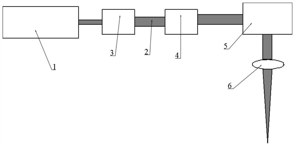
The invention relates to a laser hole making device and method. The hole making device comprises a laser source, a beam expander group, a laser self-rotating device and a scanning galvanometer device,wherein the laser source is used for outputting laser beams along a center axis of a conduction light path; the beam expander group comprises a convex lens and a concave lens, the separation distanceof which can be adjusted, and the laser beams passing through the beam expander group are incident to the laser self-rotating device; the laser self-rotating device is used for deviating the laser beams at an adjustable deviation radius to the center axis of the conduction light path to form a round ring facula, and the round ring facula is incident to the scanning galvanometer device; the scanning galvanometer device is used for rotating the round ring facula around the center axis of a focusing lens to form a plurality of concentric tracks, the focused tracks are used for scanning a processed hole to a target bore diameter after focusing, and the target bore diameter is preset. The laser hole making device can reduce the hole making tamper to improve the hole making efficiency and further can reduce influence of change of a focal position or a wall thickness to consistence of the bore diameter.

Description

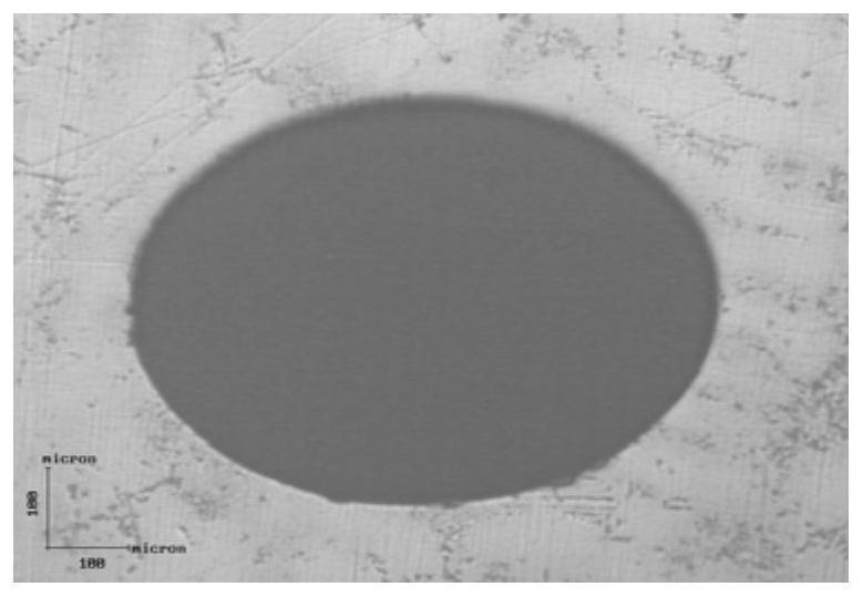
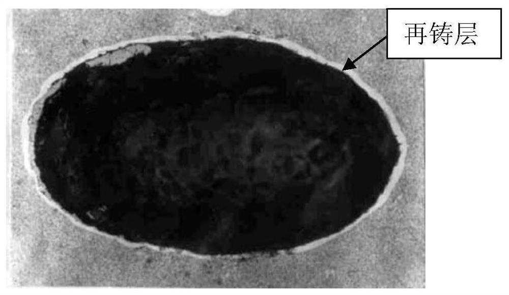
technical field [0001] The invention relates to the technical field of laser processing equipment, in particular to a laser hole-making device and method. Background technique [0002] Ultrafast lasers usually refer to femtosecond (10 ps) pulse widths less than 10 ps. -15 s) Laser, picosecond (10- 12 s) Laser, because the action time is very short, the laser power density is extremely high (over 10 12 w / cm 2 ), so there is almost no thermal diffusion in the process of removing the material, and the material removal is non-thermal melting. Therefore, ultrafast laser can be used to process small holes with no heat-affected zone, recast layer, and micro-cracks on the hole wall. figure 1 . while milliseconds (10 -3 s) Laser processing of small holes with longer pulse widths is difficult to avoid the recast layer on the hole walls of the small holes, see appendix figure 2 . [0003] Air film holes in aero-engine single crystal turbine blades require no recast layer, micr...

Claims


Application Information

Patent Timeline
Patent Type & Authority Applications(China)
IPC IPC(8): B23K26/06B23K26/382B23K26/70
CPCB23K26/0648B23K26/382B23K26/702
Inventor 张晓兵纪亮蔡敏李元成焦佳能张伟
Owner AVIC BEIJING AERONAUTICAL MFG TECH RES INST
Learn More