Automatic canning equipment for soy sauce production
An automatic and canning technology, applied in application, packaging, bottling machines, etc., can solve the problems of heavy workload, pouring, and low efficiency of soy sauce canning
- Summary
- Abstract
- Description
- Claims
- Application Information
AI Technical Summary
Problems solved by technology
Method used
Image
Examples
Embodiment 1
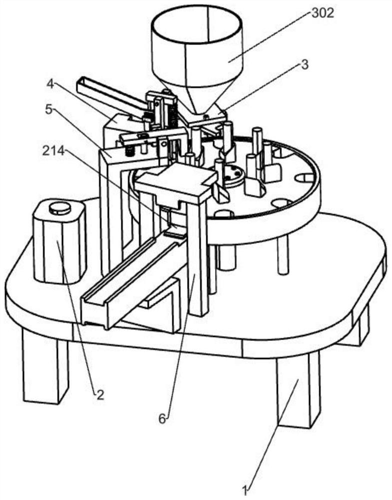
[0030] A kind of automatic canning equipment for soy sauce production, such as figure 1 As shown, it includes a workbench 1, an intermittent rotation mechanism 2 and a blanking mechanism 3, an intermittent rotation mechanism 2 is installed on the workbench 1, and a blanking mechanism 3 is installed on the left rear side workbench 1 of the intermittent rotation mechanism 2. Material mechanism 3 cooperates with intermittent rotation mechanism 2.
[0031] When soy sauce needs to be canned, the user pours an appropriate amount of soy sauce into the feeding mechanism 3, then the user places an appropriate amount of soy sauce bottle on the intermittent rotation mechanism 2, and then the user rotates the soy sauce bottle through the intermittent rotation mechanism 2, when When the soy sauce bottle rotates and is positioned directly below the unloading mechanism 3, the soy sauce in the unloading mechanism 3 flows downwards into the bottle, thus realizing the canning of soy sauce, ther...
Embodiment 2
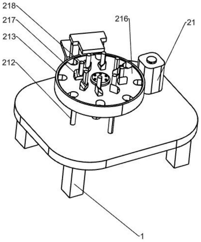
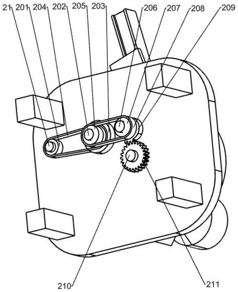
[0033] On the basis of Example 1, such as figure 1 , figure 2 and image 3As shown, the intermittent rotation mechanism 2 includes a servo motor 21, a first pulley 201, a first rotating shaft 202, a second pulley 203, a flat belt one 204, a third pulley 205, a second rotating shaft 206, and a fourth pulley 207, flat belt two 208, missing gear 209, third rotating shaft 210, spur gear 211, pillar 212, positioning plate 213, groove plate 216, contact block one 217 and contact rod one 218, servo motor 21 is installed on the workbench 1 , the output shaft of the servo motor 21 passes through the workbench 1, the first pulley 201 is installed on the output shaft of the servomotor 21, and the first rotating shaft 202 is installed in a rotational manner on the workbench 1 on the right side of the first pulley 201, the second A rotating shaft 202 is provided with a second pulley 203, a flat belt 204 is wound between the second pulley 203 and the first pulley 201, and a third belt is...
Embodiment 3
[0038] On the basis of Example 2, such as figure 1 , Figure 5 , Figure 6 and Figure 7 As shown, it also includes a capping mechanism 4, and the capping mechanism 4 includes a support two 41, a feeding pipe 401, a bottle cap conveying platform 402, an L-shaped block 403, a spring two 404, a tightening block 405, a swing plate, and a guide sleeve 406, push rod 1 407, contact block 2 408, spring 3 409, push rod 2 410 and bearing block 412, support 2 41 is fixedly connected to the workbench 1 on the front side of support 301, and support 2 41 is embedded with blanking Pipe 401, the upper part of the outer wall of the feeding pipe 401 is provided with a bottle cap conveying platform 402, the front and rear sides of the right part of the bottle cap conveying platform 402 are all fixedly connected with an L-shaped block 403, and the L-shaped block 403 is connected with a spring 2 404, A clamping block 405 is fixed on the spring two 404, and the clamping block 405 and the bottle...
PUM
 Abstract
Description
Claims
Application Information
 - R&D
- Intellectual Property
- Life Sciences
- Materials
- Tech Scout
- Unparalleled Data Quality
- Higher Quality Content
- 60% Fewer Hallucinations
Browse by: Latest US Patents, China's latest patents, Technical Efficacy Thesaurus, Application Domain, Technology Topic, Popular Technical Reports.
© 2025 PatSnap. All rights reserved.Legal|Privacy policy|Modern Slavery Act Transparency Statement|Sitemap|About US| Contact US: help@patsnap.com


