
VVS engine rotary variable-valve-timing structure

A valve timing and rotary technology, applied to engine components, machines/engines, mechanical equipment, etc., can solve problems such as small valve overlap angle, high engine valve lift, and abnormal noise of the pin shaft

Pending Publication Date: 2020-10-20
LUOYANG NORTHERN EK CHOR MOTORCYCLE CO LTD
View PDF0 Cites 2 Cited by
  • Summary
  • Abstract
  • Description
  • Claims
  • Application Information

AI Technical Summary

Problems solved by technology

[0003] The current variable valve timing structure of motorcycle single-cylinder engines mostly adopts double intake rocker arm components with pin (hole-hole-shaft) synchronous type. The two intake rocker arms work separately (the rocker arm that cooperates with the low-speed intake cam drives the valve to inhale, and the other intake rocker arm cooperates with the high-speed intake cam, which only rotates and does not perform any action on the valve), at this time The engine valve lift is low and the valve overlap angle is small; when the engine is operating at high speed (when the engine speed reaches the design requirement value), the pin is pushed into the pin hole of the double intake rocker arm by the electromagnet, and the two intake rocker arms are synchronized , at this time, the double intake rocker arm moves with the high-speed cam profile of the camshaft to drive the intake valve to inhale air, so that the engine valve lift is high and the valve overlap angle is large; It requires high precision, takes up a lot of space, high manufacturing and maintenance costs, and has the defect that the pin shaft produces abnormal noise when performing the insertion action

Method used


Image

  • VVS engine rotary variable-valve-timing structure
  • VVS engine rotary variable-valve-timing structure
  • VVS engine rotary variable-valve-timing structure

Examples


Embodiment Construction

[0033] The present invention will be further described in detail below in conjunction with the accompanying drawings.

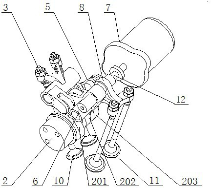
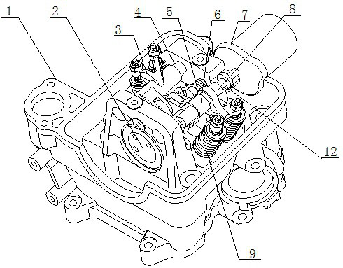
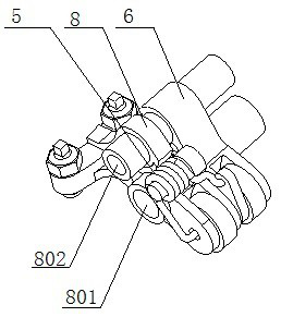
[0034] like figure 1 , figure 2 , Figure 11 , Figure 12 , Figure 13 , Figure 14 As shown, a VVS engine rotary variable valve timing structure includes a camshaft 2, an exhaust rocker arm assembly, a high-speed intake rocker arm 6, and a low-speed intake rocker arm 8. The camshaft 2 is rotatable set on the engine cylinder head 1, the camshaft 2 is provided with an exhaust cam 201, a high-speed intake cam 202 and a low-speed intake cam 203, and the exhaust rocker arm assembly is arranged on the side of the camshaft 2 corresponding to the exhaust cam 201. The high-speed intake rocker arm 6 and the low-speed intake rocker arm 8 are respectively arranged on the other side of the camshaft 2 corresponding to the high-speed intake cam 202 and the low-speed intake cam 203. The exhaust rocker arm assembly includes the exhaust rocker arm 3 And the exhaust roc...


PUM


Abstract

The invention relates to a VVS engine rotary variable-valve-timing structure. The structure comprises a camshaft, an exhaust rocker arm assembly, a high-speed air inlet rocker arm and a low-speed airinlet rocker arm, and further comprises a synchronous torsional spring, a synchronous plug, an electromagnet and a reset compressed spring. The fixed end of the synchronous torsional spring is fixedlyconnected with the low-speed air inlet rocker arm, the working end of the synchronous torsional spring is fixedly connected with the high-speed air inlet rocker arm, in this way, when an engine worksat a low speed, the high-speed air inlet rocker arm does not make contact with a high-speed air inlet cam of the camshaft, and the camshaft cooperates with the low-speed air inlet rocker arm througha low-speed air inlet cam. The synchronous plug is used for controlling the cooperation state between the high-speed air inlet rocker arm and the high-speed air inlet cam, and comprises a first stepped shaft, a second stepped shaft and a transitional frustum which are arranged coaxially, the second stepped shaft is arranged inside the high-speed air inlet rocker arm, and the reset compressed spring is arranged at the other end of the second stepped shaft. The overall structural size of the structure is small, the manufacturing precision is low, and abnormal sounds are avoided during working.

Description

technical field [0001] The invention relates to motorcycle engine technology, in particular to a VVS engine rotary variable valve timing structure. Background technique [0002] The variable valve timing structure (Variable Valve Timing and Valve Lift Smart System, VVS for short) is a structure that can make the engine play the best performance under different working conditions. At the same time, the driving structure is switched between cams with different cam surfaces by rotating and separating the rocker arm to change the valve timing (valve lift, valve overlap angle), thereby changing the operating state of the engine. [0003] The current variable valve timing structure of motorcycle single-cylinder engines mostly adopts double intake rocker arm components with pin (hole-hole-shaft) synchronous type. The two intake rocker arms work separately (the rocker arm that cooperates with the low-speed intake cam drives the valve to inhale, and the other intake rocker arm coope...

Claims


Application Information

Patent Timeline
IPC IPC(8): F01L13/00F01L1/26
CPCF01L1/267F01L13/0015F01L13/0036
Inventor 周传珂辛悦陈献昌闫睿
Owner LUOYANG NORTHERN EK CHOR MOTORCYCLE CO LTD
Learn More