
A grating splicing device

A splicing device and grating technology, which is applied in the field of diffraction gratings, can solve problems such as grating base deformation, many parts, and affect the quality of grating splicing, and achieve the effects of ensuring high precision, reducing splicing errors, and improving grating splicing quality

Active Publication Date: 2021-12-31
CHANGCHUN INST OF OPTICS FINE MECHANICS & PHYSICS CHINESE ACAD OF SCI
View PDF11 Cites 0 Cited by
  • Summary
  • Abstract
  • Description
  • Claims
  • Application Information

AI Technical Summary

Problems solved by technology

[0003] The existing production methods of spliced ​​gratings mainly include two types: one is spliced ​​gratings including mechanical adjustment devices, application number: CN201610541867.7, "an array type grating splicing adjustment device driven by macro-micro combination", which requires precise The mechanical adjustment device can obtain high-quality spliced ​​grating, but the whole device has many parts and complex structure, which is not conducive to the long-term stability of the grating splicing quality. The deformation caused by the different temperature changes of the adjustment device and the grating blank will affect the grating. Stitching quality; Another method is to make large-area spliced ​​gratings by splicing and duplication methods, application number: CN201510190510.4, "Copying and splicing method for large-scale planar diffraction gratings", which is conducive to long-term storage of gratings, but grating duplication and curing The process will cause deformation of the grating substrate, which is not conducive to the production of high-quality spliced ​​gratings
[0004] Therefore, how to provide a grating splicing device that solves the problem that the existing spliced ​​gratings cannot take into account both the splicing quality of the grating and the long-term stability of the grating is a technical problem urgently needed by those skilled in the art.

Method used


Image

  • A grating splicing device
  • A grating splicing device
  • A grating splicing device

Examples


Embodiment Construction

[0023] The following will clearly and completely describe the technical solutions in the embodiments of the present invention with reference to the accompanying drawings in the embodiments of the present invention. Obviously, the described embodiments are only some, not all, embodiments of the present invention. Based on the embodiments of the present invention, all other embodiments obtained by persons of ordinary skill in the art without making creative efforts belong to the protection scope of the present invention.

[0024] In order to enable those skilled in the art to better understand the solution of the present invention, the present invention will be further described in detail below in conjunction with the accompanying drawings and specific embodiments.

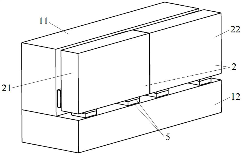
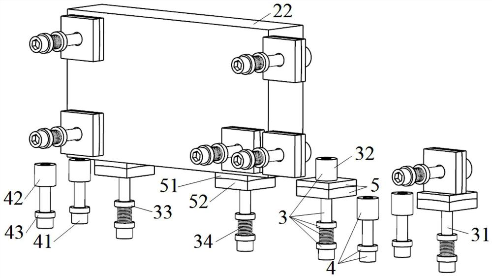
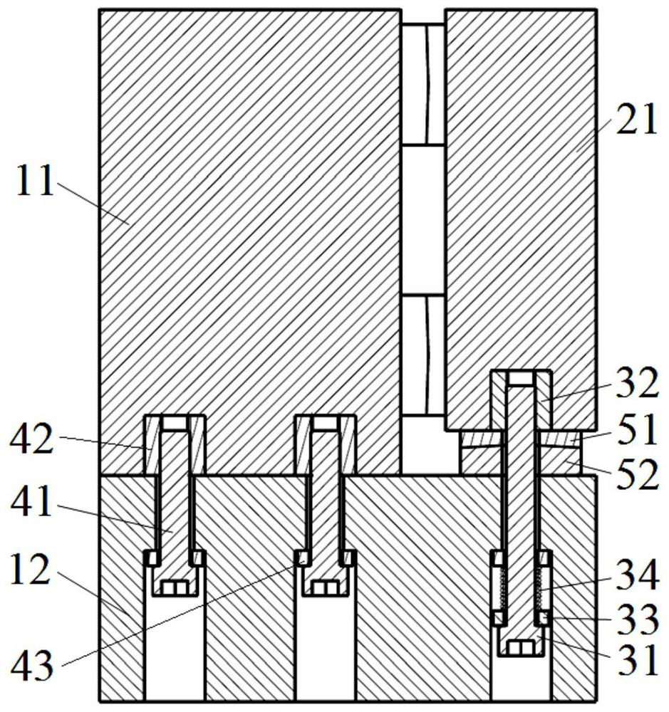
[0025] Please refer to Figure 1 to Figure 3 ,in, figure 1 It is a schematic diagram of the main visual axis side of the grating splicing device provided by the embodiment of the present invention, figure 2 A sch...


PUM


Abstract

The invention discloses a grating splicing device, which includes a base body and at least two gratings to be spliced. Several first fastening mechanisms for fixing the grating to the base body are arranged between the base body and the gratings. A grindable adjustment mechanism is also provided between the base body and the grating. The above-mentioned grating splicing device reduces splicing errors by grinding to achieve high-precision splicing of gratings. While satisfying the splicing quality, it has a simple structure and is easy to manufacture, which is conducive to the long-term stability of grating splicing quality and has high precision and high stability of grating splicing. sexual characteristics.

Description

technical field [0001] The invention relates to the technical field of diffraction gratings, in particular to a grating splicing device. Background technique [0002] Diffraction grating is a kind of optical element with nanometer precision, which is the core component of spectroscopic instruments, and is widely used in astronomy, national defense, industry, agriculture and other fields. The concept of grating splicing was first proposed from the spectroscopic instruments of large astronomical telescopes. In order to improve the light-gathering ability and resolving power of astronomical telescope systems, meter-level gratings are needed for spectral analysis; in addition, with the continuous development of laser inertial confinement fusion research To develop, large-size planar diffraction gratings become the key to increasing the output laser pulse energy, and it is necessary to solve the production problems of large-size gratings, such as grating splicing technology. [...

Claims


Application Information

Patent Timeline
Patent Type & Authority Patents(China)
IPC IPC(8): G02B7/00
CPCG02B7/00
Inventor 糜小涛张善文齐向东林雨江思博周敬萱杨国军
Owner CHANGCHUN INST OF OPTICS FINE MECHANICS & PHYSICS CHINESE ACAD OF SCI
Learn More