
Image segmentation device for astronomical optical fiber aiming

A technology of slicing device and optical fiber, which is applied in the coupling of optical waveguides, light guides, optics, etc., can solve the problems of inability to detect signal response, existence of detection blind spots, and low fiber coupling efficiency.

Active Publication Date: 2020-10-20
HARBIN ENG UNIV
View PDF7 Cites 2 Cited by
  • Summary
  • Abstract
  • Description
  • Claims
  • Application Information

AI Technical Summary

Problems solved by technology

However, this positioning method requires multiple position iterations. It cannot be observed while positioning, and it cannot monitor the relative position of the image spot and the fiber core in real time. The tracking accuracy cannot be guaranteed, and the observation efficiency is low.
The embedded multi-core optical fiber sight and positioning device described in Chinese patent CN104898214A uses multi-core optical fiber to perform real-time monitoring and optical fiber aiming of the relative position of the light spot and the core of the scientific main optical fiber. The efficiency is not high, and when the image spot falls between the scientific main fiber and the side fiber, the signal response cannot be detected, and there is a detection blind zone

Method used


Image

  • Image segmentation device for astronomical optical fiber aiming
  • Image segmentation device for astronomical optical fiber aiming
  • Image segmentation device for astronomical optical fiber aiming

Examples


Embodiment Construction

[0022] The present invention is described in more detail below in conjunction with accompanying drawing example:

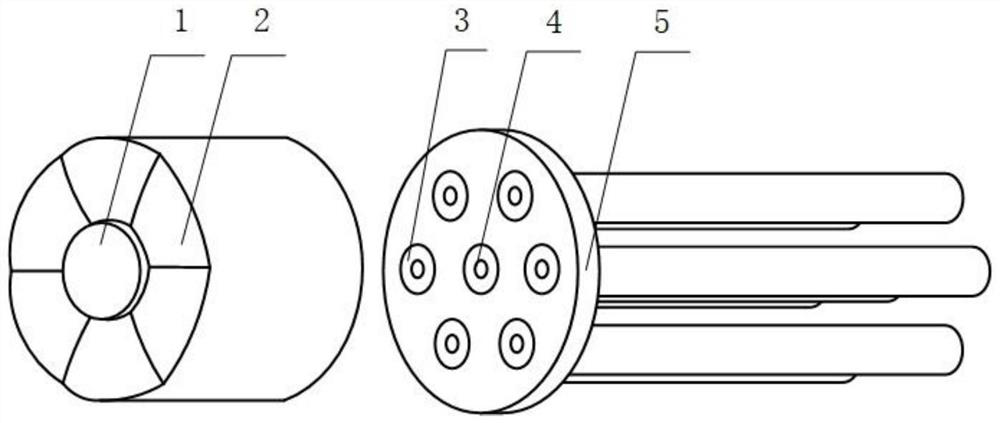
[0023] see figure 1 , the image splitting device for aiming at astronomical optical fibers of the present invention comprises a special-shaped microlens array composed of a central circular plate 1 and a plurality of fan-shaped microlenses 2, and consists of a central scientific main optical fiber 4 and a plurality of side optical fibers 3 around fiber optic bundle. The quartz microwell plate 5 is distributed around the scientific main optical fiber 4 according to the axis of the circular plate 1 in the axis center of the scientific main optical fiber 4, and a plurality of side optical fibers 3 according to a certain radius, and the axis center of each side optical fiber 3 is aligned with a The optical axis of the fan-shaped micro-lens 2 is aligned, and the side optical fiber 3 should be completely covered by the fan-shaped micro-lens 2 .

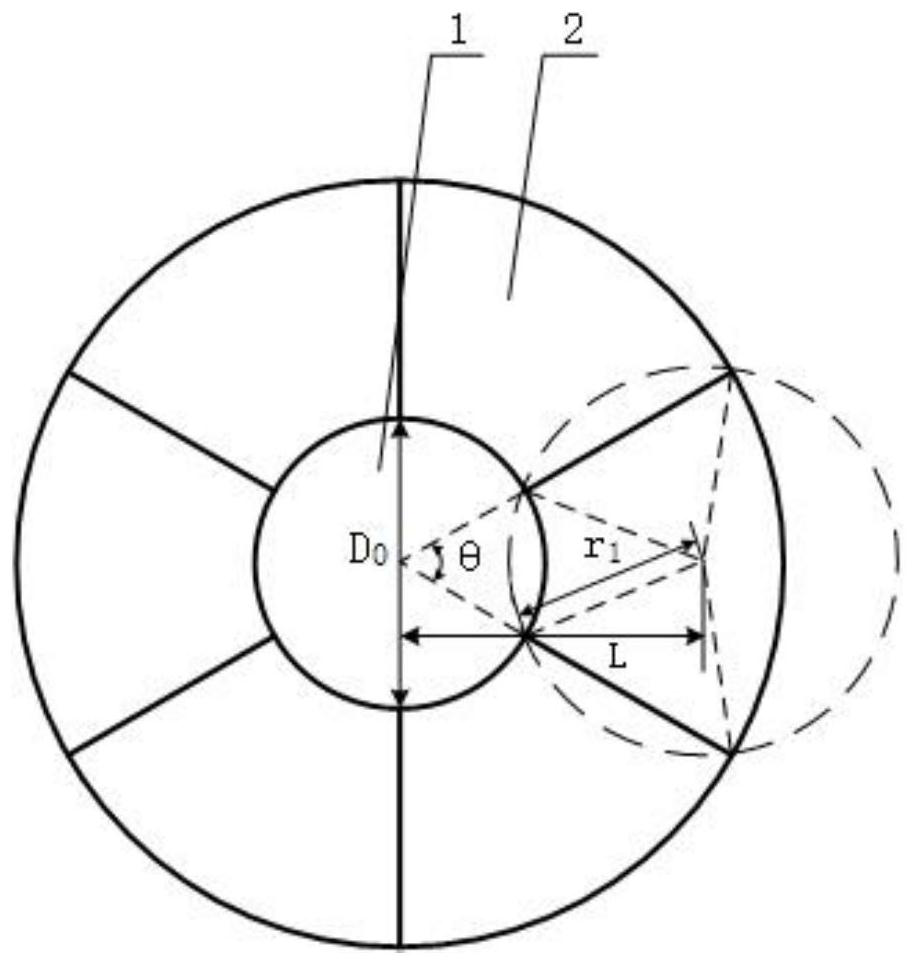
[0024] see figure 2...


PUM


Abstract

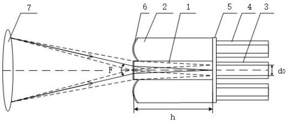
The invention relates to the technical field of astronomical optical fiber aiming, and in particular relates to an image segmentation device for astronomical optical fiber aiming. The device comprisesa special-shaped micro-lens array and an optical fiber bundle. The special-shaped micro-lens array is composed of a central circular flat plate and a plurality of fan-shaped micro-lenses around the central circular flat plate. According to the invention, the special-shaped micro-lens array with the circular flat plate structure at the center and a plurality of fan-shaped micro-lenses at the periphery is adopted, 100% coverage of light field energy is realized without changing the incident light focal ratio of the scientific main optical fiber, i.e., light deviating from the scientific main optical fiber is coupled into the side optical fiber by the fan-shaped micro-lenses, and a detection blind area does not exist.

Description

technical field [0001] The invention relates to the technical field of astronomical optical fiber aiming, in particular to an image splitting device for astronomical optical fiber aiming. Background technique [0002] The acquisition and analysis of astronomical spectra is an important means of studying celestial bodies in astronomy. Using the spectra of celestial bodies, astronomers can obtain characteristic parameters such as the chemical composition of celestial bodies, celestial body density, pressure, temperature, magnetic field and movement speed, which are of great significance for human beings to explore space, understand unknown celestial bodies, and find new homes suitable for human habitation. [0003] Since the optical fiber was first applied to the optical signal transmission network of the telescope in 1981, it has caused revolutionary development in the field of astronomical observation technology because of its long-distance transmission of light, flexibility...

Claims


Application Information

Patent Timeline
IPC IPC(8): G02B23/00G02B23/12G02B6/38G02B3/00G02B1/11
CPCG02B23/00G02B23/12G02B6/3853G02B3/0006G02B1/11
Inventor 孙伟民王佳斌耿涛王安之闫奇金夕人陈旭东朱清柱陈龙震张英华
Owner HARBIN ENG UNIV
Learn More