Sweepforward front edge type side plate structure matched with binary supersonic air inlet channel

A supersonic inlet, dual-type technology, applied in the field of aerodynamics, can solve the problem of changing the two-dimensional flow characteristics of the inlet, the difference in the recovery coefficient of the total pressure of the inlet, and the lateral overflow of the compression section of the inlet, etc. question

Pending Publication Date: 2020-10-20
NANJING UNIV OF AERONAUTICS & ASTRONAUTICS
View PDF0 Cites 2 Cited by
  • Summary
  • Abstract
  • Description
  • Claims
  • Application Information

AI Technical Summary

Problems solved by technology

[0003] The flow field of the compression section of the binary supersonic inlet is generally designed as a two-dimensional flow, but in the actual flow situation, considering the integrated design of the inlet / body, due to the low pressure on both sides of the inlet, the A transverse pressure gradient will be generated in front of the lip, which will cause lateral overflow in the compression section of the intake port and change the two-dimensional flow characteristics of the intake port
But at the same time, after the airflow passes through the precursor, the boundary layer thickens, and under the cover of the side plate, the low-energy flow of the boundary layer can continue to develop, resulting in a poor total pressure recovery coefficient of the inlet

Method used


Image

  • Sweepforward front edge type side plate structure matched with binary supersonic air inlet channel
  • Sweepforward front edge type side plate structure matched with binary supersonic air inlet channel
  • Sweepforward front edge type side plate structure matched with binary supersonic air inlet channel

Examples


Embodiment

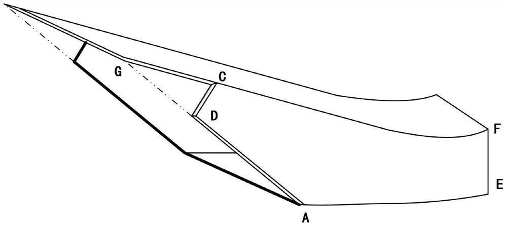
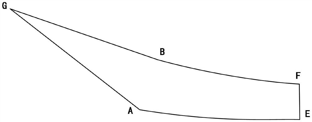
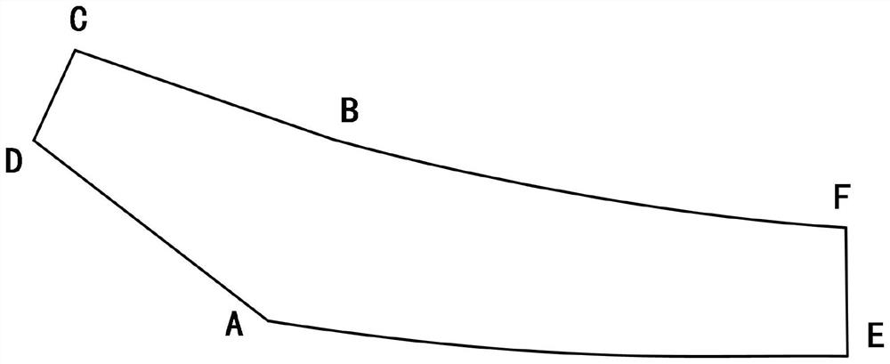
[0037] Embodiment: Based on the traditional binary supersonic inlet, in order to weaken the lateral overflow effect in front of the lip, side plate structures are often added on both sides of the front body of the inlet to reduce the lateral overflow of the compression section and weaken the intake The three-dimensional flow effect of the channel is used to ensure the two-dimensional characteristics of the flow field in the compression section. Although in general, with the increase of side plate shading, the flow capture coefficient of the intake will increase. But at the same time, after the airflow passes through the precursor, the boundary layer becomes thicker. Under the cover of the side plate, the low-energy flow of the boundary layer can continue to develop, which will cause the total pressure recovery coefficient of the inlet port to be poor. Therefore, this embodiment redesigns the structure of the side plate, and the main idea is to design the front edge line of the...


PUM


Abstract

The invention discloses a sweepforward front edge type side plate structure matched with a binary supersonic air inlet channel. The sweepforward front edge type side plate structure comprises a side plate, wherein the section of the side plate is defined by an upper wing contour line, a rear edge contour line, a lower wing contour line and a front edge contour line which are connected end to end;the upper wing contour line, the rear edge contour line and the lower wing contour line are determined by profile parameters of the air inlet channel; the front edge contour line has a sweepforward angle, and the lower side edge of the sweepforward angle coincides with a shock wave line generated by a last-stage compression inclined plate under the condition of the highest flight Mach number. According to the sweepforward front edge type side plate structure, the air inlet channel / airframe integrated design is considered, and the sweepforward front edge type side plate structure is used, thusthe transverse overflow effect caused by the transverse pressure gradient in front of a lip can be weakened, so that the flow capture coefficient is increased, further the transverse pressure difference between the compression inclined plate and the outer side of the machine body can be used for effectively moving a boundary layer of the airframe and the compression inclined plate, the total pressure of airflow captured by the air inlet channel is increased, the internal flow quality of the air inlet channel is improved, and the starting capacity of the air inlet channel is guaranteed.

Description

technical field [0001] The invention relates to the field of aerodynamics, in particular to a side plate structure matched with a supersonic air inlet. Background technique [0002] The supersonic air inlet refers to a section of pipeline through which the jet passes from the inlet of the aircraft (or the inlet of the engine nacelle) to the inlet of the engine on a supersonic aircraft whose Mach number is greater than 1.6 to 1.7. As an important component, the supersonic intake port has a direct impact on the performance of the engine. It is required to have a good starting ability in a wide range of Mach numbers, and at the same time ensure a high flow coefficient, total pressure recovery coefficient and Good outlet flow quality and sufficient ability to resist back pressure. [0003] The flow field of the compression section of the binary supersonic inlet is generally designed as a two-dimensional flow, but in the actual flow situation, considering the integrated design o...

Claims


Application Information

Patent Timeline
IPC IPC(8): G06F30/15F02C7/04G06F119/14
CPCG06F30/15F02C7/04G06F2119/14Y02T90/00
Inventor 黄国平王瑞琳俞宗汉郝常凯
Owner NANJING UNIV OF AERONAUTICS & ASTRONAUTICS
Why Eureka
Try Eureka