Recyclable biliary tract drainage tube coated stent

A technology of covered stents and drainage tubes, applied in the field of medical supplies, can solve the problems of easy recurrence, easy blockage of plastic stents, displacement, metal stent stimulation, etc.

Pending Publication Date: 2020-10-23
高海军
View PDF0 Cites 0 Cited by
  • Summary
  • Abstract
  • Description
  • Claims
  • Application Information

AI Technical Summary

Problems solved by technology

However, in these two methods, stenosis is easy to recur, plastic stents are

Method used


Image

  • Recyclable biliary tract drainage tube coated stent
  • Recyclable biliary tract drainage tube coated stent
  • Recyclable biliary tract drainage tube coated stent

Examples


Embodiment 1

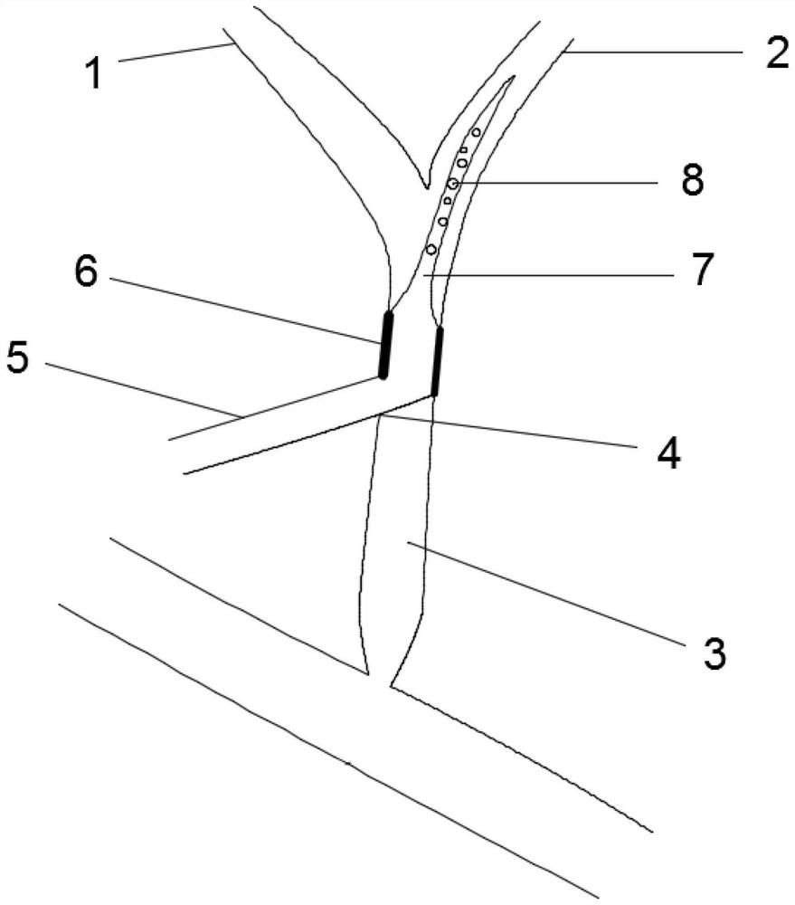
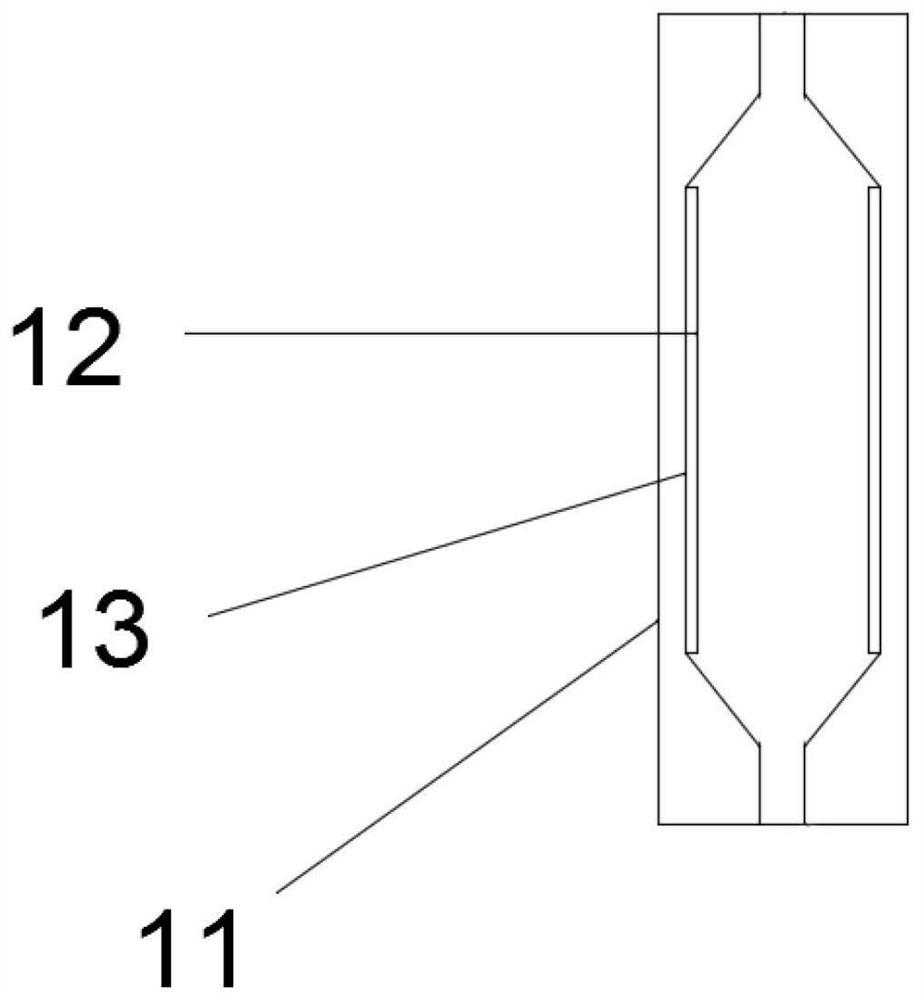
[0041] Example 1: Such as figure 1 As shown, it is a schematic diagram of puncture and drainage in the body. During the operation, the drainage tube 10 is extended into the common bile duct 3 through the surgical incision 4, the posterior drainage tube 7 is inserted into the left hepatic duct 2 along the common bile duct 3, and the stent graft 6 Place it at the bile duct leakage point or bile duct stenosis, and then slowly withdraw the cannula 11 outwards. As the cannula 11 is withdrawn, the internal stent 12 will automatically expand. Self-expandable stents or cones can be used for intracorporeal puncture A self-expanding stent. The stent 12 stretches the covering film 13 and the stretched covering film 13 is tightly attached to the inner wall of the common bile duct 3. The covering film 13 directly blocks the leakage of the bile duct, and the stent 12 directly expands the narrowed bile duct. After that, the drainage work can be performed through the drainage hole 8, and at the...

Embodiment 2

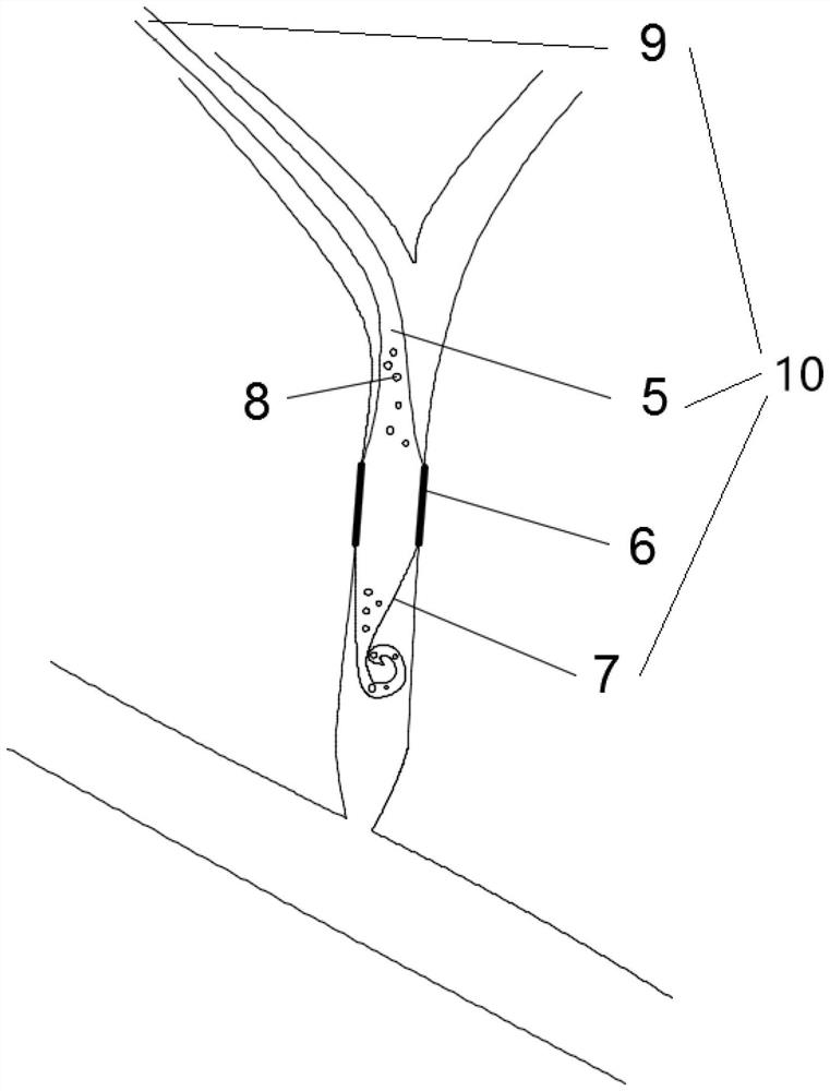
[0043] Example 2: Such as figure 2 As shown, it is a schematic diagram of extracorporeal puncture and drainage. During the operation, the drainage tube 10 is extended into the liver along the incision outside the body, and the posterior drainage tube 7 is inserted into the common bile duct 3 along the right hepatic duct 1. The posterior drainage tube used for external puncture 7 is a coiled tube body, the length of the crimped posterior drainage tube 7 is 4cm, and the length of the common bile duct 3 is 8-12cm, which effectively avoids the problem of drainage failure caused by the posterior drainage tube 7 passing through the common bile duct 3 into the duodenum. The irritation of the drainage tube 10 to the intestine is also avoided. When the stent graft 6 enters the leak point of the bile duct or the narrow part of the bile duct, the cannula 11 is slowly withdrawn. As the cannula 11 is withdrawn, the stent 12 will cover the membrane 13 Expanded, the membrane 13 will fit with ...


PUM

PropertyMeasurementUnit
Lengthaaaaaaaaaa
Lengthaaaaaaaaaa
Diameteraaaaaaaaaa

Abstract

The invention provides a recyclable biliary tract drainage tube coated stent. The recyclable biliary tract drainage tube coated stent comprises a coated stent, a drainage tube and a sleeve. The drainage tube comprises an outer drainage tube, a front drainage tube and a rear drainage tube, the front drainage tube is arranged at one end of the outer drainage tube, the rear drainage tube is arrangedat one end of the front drainage tube away from the outer drainage tube, the coated stent is arranged at the boundary between the front drainage tube and the rear drainage tube, the coated stent includes a stent and a coating, the stent is inserted into the drainage tube, the end of the conical part of the distal end of the stent is inserted into the side wall of the rear drainage tube, the coating is arranged on the outside of the stent in a sleeved mode, two ends of the coating are arranged on the outside of the drainage tube in a sleeved mode, the connection part between the coating and thedrainage pipe is provided with mesh-like through holes, the outer part of the coated stent is sleeved with the sleeve, the sleeve is sleeved outside the outer drainage tube and the front drainage pipe, and a plurality of drainage holes are arranged on the surface of the rear drainage tube. Beneficial effects of the invention are that: the biliary stricture site can be supported and the biliary leakage can be sealed and blocked while carrying out biliary drainage, and the invention is a recyclable stent device.

Description

Technical field [0001] The invention belongs to the field of medical supplies, and in particular relates to a biliary tract recoverable drainage tube covered stent. Background technique [0002] Bile duct stenosis can be cancerous or benign. Benign stenosis can be caused by surgical injury or trauma, pancreatic inflammation, scarring or hardening of bile duct tissue caused by chronic inflammation, recurrent gallstones, or poor tissue reconnection after liver transplantation. The incidence of biliary complications after liver transplantation is about 5% to 34%, and biliary anastomotic stenosis accounts for about 40% of biliary complications. As the number of cases of cholecystectomy increases, the incidence of benign biliary strictures also increases. Surgery has played an important role in the treatment of benign biliary strictures, but it is accompanied by serious complications and mortality. At present, minimally invasive endoscopic or percutaneous biliary puncture stent plac...

Claims


Application Information

Patent Timeline
IPC IPC(8): A61F2/04A61M25/14A61M25/04
CPCA61F2/04A61F2002/041A61F2210/0061A61M25/0026A61M25/0043A61M25/0045A61M25/007A61M25/04A61M2025/0063A61M2210/1075A61M2210/005
Inventor 高海军
Owner 高海军
Why Eureka
Try Eureka