
Cleaning equipment for automobile parts

A technology for cleaning equipment and spare parts, applied to lighting and heating equipment, cleaning methods using tools, cleaning methods using liquids, etc., can solve problems such as unfavorable use of accessories, poor cleaning quality, and a large amount of labor

Inactive Publication Date: 2020-10-23
杭州巾成科技有限公司
View PDF11 Cites 9 Cited by
  • Summary
  • Abstract
  • Description
  • Claims
  • Application Information

AI Technical Summary

Problems solved by technology

Traditionally, most of the cleaning of auto parts is to put the parts into the water, and the cleaning personnel will use the brush to clean the parts one by one. This cleaning method not only wastes time and has low cleaning efficiency, but also requires a lot of labor and increases High labor intensity increases the cleaning cost; the existing auto parts cleaning equipment on the market only uses water to clean the parts, the cleaning efficiency is low, the cleaning quality is poor, and the parts cannot be cleaned in all directions, and the parts There may be a lot of waste and other impurities on the surface, which cannot be washed away after washing with water, so that the cleaned parts cannot meet the cleaning requirements; moreover, the cleaned water cannot be filtered, so that the water source and parts are mixed together. It is beneficial to the processing and use of subsequent spare parts; there is also the existing spare parts cleaning equipment that does not have the function of drying the cleaned parts, resulting in a lot of residual moisture on the cleaned parts, which not only easily leads to rusting of parts, but also is not conducive to The subsequent use of accessories requires additional drying equipment for drying, which not only increases the cost, but also reduces the efficiency of the production and processing of accessories, which cannot meet people's needs

Method used


Image

  • Cleaning equipment for automobile parts
  • Cleaning equipment for automobile parts
  • Cleaning equipment for automobile parts

Examples


Embodiment 1

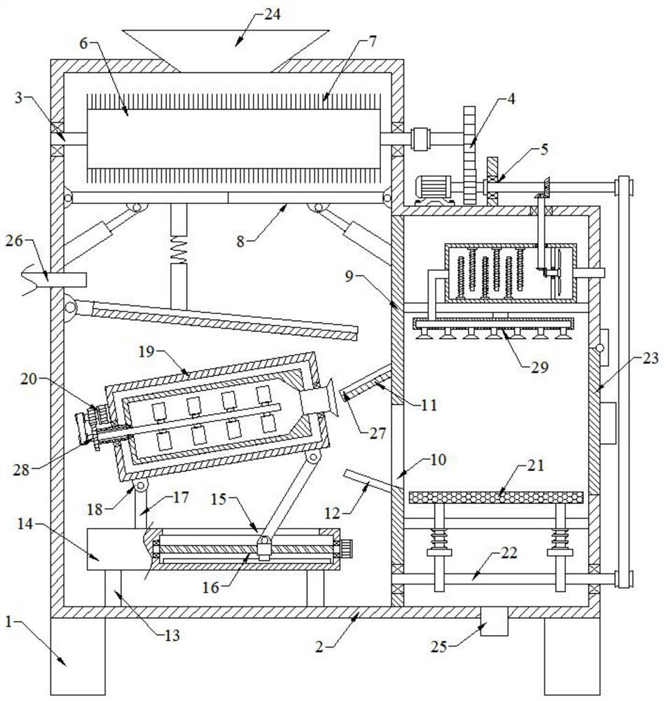
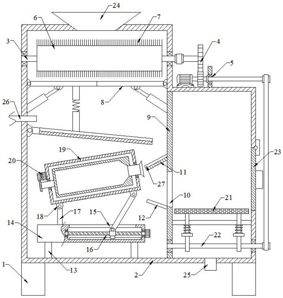
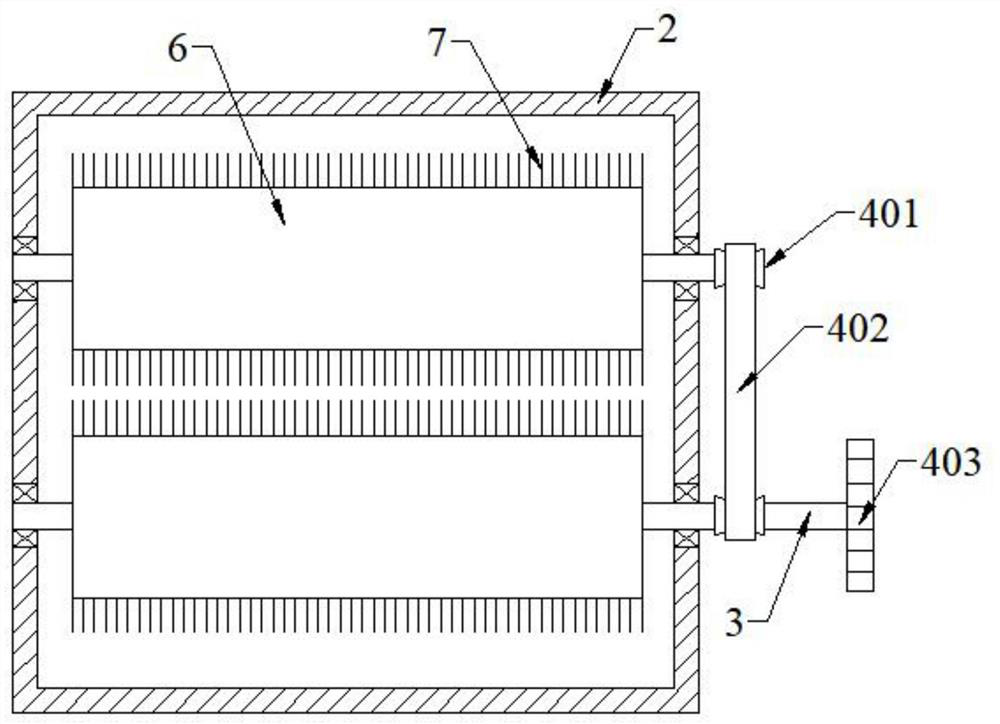
[0048] Please refer to the accompanying drawings, the present embodiment is a kind of cleaning equipment for auto parts, including two sets of supports 1, the upper end of the support 1 is fixed with a cleaning box 2, and the left and right side walls of the inner cavity of the cleaning box 2 are rotatably connected with two A first rotating shaft 3, the right end of the first rotating shaft 3 is connected with a rotating assembly 4, the rotating assembly 4 is connected with a linkage assembly 5, both first rotating shafts 3 are provided with cleaning rollers 6, and the side walls of the cleaning rollers 6 are evenly provided with cleaning brushes 7. A blanking assembly 8 is installed in the middle of the inner cavity of the cleaning box 2. A partition 9 is fixedly connected between the upper and lower walls of the inner cavity of the cleaning box 2. The middle part of the partition 9 is provided with a feeding trough 10. The left end of the partition 9 is fixed with a lower Th...

Embodiment 2

[0067] Please refer to the accompanying drawings, on the basis of Embodiment 1, it also includes a stirring assembly 28, the stirring assembly 28 includes a stirring shaft 2801, the stirring shaft 2801 is rotatably connected to the left wall of the inner cylinder 2002, and the upper and lower side walls of the stirring shaft 2801 are arranged symmetrically. There are multiple sets of stirring paddles 2802, the left end of the stirring shaft 2801 passes through the hollow shaft 2001 and is fixedly connected with the fourth pulley 2803, the third belt 2804 is installed on the fourth pulley 2803, the output end of the third servo motor 2005 is fixedly connected with the The fifth pulley 2805 and the fifth pulley 2805 are in drive connection with the fourth pulley 2803 through the third belt 2804 .

[0068] Specifically, step S7 is also included: the third servo motor 2005 rotates clockwise and at the same time drives the fifth pulley 2805 to rotate clockwise, and then drives the f...

Embodiment 3

[0070] Please refer to the accompanying drawings, on the basis of Embodiment 1, it also includes a drying assembly 29, the drying assembly 29 includes a support plate 2901, and the support plate 2901 is fixed between the right end of the partition plate 9 and the right wall of the inner cavity of the cleaning box 2 Between them, a heating box 2902 is arranged on the upper end of the support plate 2901, and multiple sets of heating tubes 2903 are installed alternately on the upper and lower walls of the inner cavity of the heating box 2902. Rod 2905, the fan blade 2906 is installed on the right end of the rotating rod 2905, the first bevel gear 2907 is fixedly connected to the left end of the rotating rod 2905, the upper wall of the heating box 2902 and the upper wall of the cleaning box 2 are rotatably connected with a third rotating shaft 2908, and the lower end of the third rotating shaft 2908 A second bevel gear 2909 is fixedly connected, the second bevel gear 2909 is meshed...


PUM


Abstract

The invention discloses cleaning equipment for automobile parts. The cleaning equipment comprises two supports, wherein a cleaning box is fixedly connected to the upper ends of the supports, a rotating assembly is connected to the right ends of first rotating shafts, a linkage assembly is connected to the rotating assembly, sweeping rollers are arranged on the two first rotating shafts, a discharging assembly is arranged in the middle of an inner cavity of the cleaning box, a lifting assembly is arranged in a supporting table, an overturning assembly is arranged in an outer cylinder, and a vibration assembly is arranged at the lower end of a filter plate; and parts are swept and brushed through sweeping brushes, a large amount of sweeps and dirt adhering to the parts can be brushed away, the parts, cleaning liquid and water in an inner barrel are driven by the overturning assembly to be overturned and cleaned, the cleaning efficiency is high, solid-liquid separation of the parts and waste liquid is achieved through the filter plate, the vibration assembly drives the filter plate to vibrate up and down in a reciprocating mode, the solid-liquid separation efficiency can be improved,parts on the filter plate are dried through a drying assembly, follow-up part treatment and use are facilitated, the cost is reduced, and the machining efficiency is improved.

Description

technical field [0001] The invention relates to the technical field of production and processing equipment for auto parts, in particular to cleaning equipment for auto parts. Background technique [0002] Automobile refers to a vehicle driven by power and has 4 or more wheels, which is mainly used to carry people and (or) goods, tow vehicles and special purposes for carrying people and (or) goods. Cars are mainly divided into passenger cars and commercial vehicles. Passenger cars are mainly used to carry passengers and their luggage and / or temporary items in terms of their design and technical characteristics, including the driver's seat. Passenger cars do not exceed 9 seats. Passenger cars are divided into the following 11 types. Mainly include: ordinary passenger cars, convertible top passenger cars, high-end passenger cars, small passenger cars, convertible cars, hatchback passenger cars, station wagons, multi-purpose passenger cars, short head passenger cars, off-road ...

Claims


Application Information

Patent Timeline
IPC IPC(8): B08B1/04B08B1/00B08B3/04B08B3/08B08B3/10B08B13/00F26B21/00
CPCB08B3/044B08B3/08B08B3/10B08B13/00F26B21/001B08B1/32B08B1/12
Inventor 徐帅
Owner 杭州巾成科技有限公司
Learn More