Tire dust removing used for new energy automobile

A technology of new energy vehicles and cleaning devices, applied in the direction of cleaning methods using gas flow, combined devices, cleaning methods and appliances, etc., which can solve problems such as economic losses, large stains on placement time, and affecting the health of staff

Inactive Publication Date: 2020-10-23
史书明
View PDF2 Cites 0 Cited by
  • Summary
  • Abstract
  • Description
  • Claims
  • Application Information

AI Technical Summary

Problems solved by technology

[0003] When most new energy vehicle tires are sold in the exhibition hall, they are placed for too long, resulting in a large amount of dust on the surface, which affects their appearance, reduces sales, and causes economic losses. Therefore, it is necessary to clean the wheels
However, most of the existing cleaning devices are open-air operations, which are likely to cause dust to fly and affect the health of the staff after inhalation. For example, the Chinese invention application document with the patent number CN201710477323.3 discloses a new energy vehicle wheel. Advanced dust cleaning device, place the tire between the fixed blocks, and use the arc-shaped brush to clean it. The arc-shaped brush will sweep the dust on the tire and scatter around. The dust floating on the work site needs to be cleaned to increase the work intensity.
Or use water to clean the tires. For example, the patent number is CN201810902736.6 Chinese invention application document, which discloses a dust cleaning device for new energy vehicle wheels. The water in the water tank is pumped up and cleaned by the nozzle. The cleaning water is filtered by the filter and then recycled and reused. However, the filtering effect of the filter cannot be guaranteed. The cleaning water is very dirty. Once the filter is not complete, cleaning the tire will only make it worse. Dirty, you need to change the water and clean it again, which not only takes a long time, but also increases water consumption

Method used


Image

  • Tire dust removing used for new energy automobile
  • Tire dust removing used for new energy automobile
  • Tire dust removing used for new energy automobile

Examples


Embodiment 1

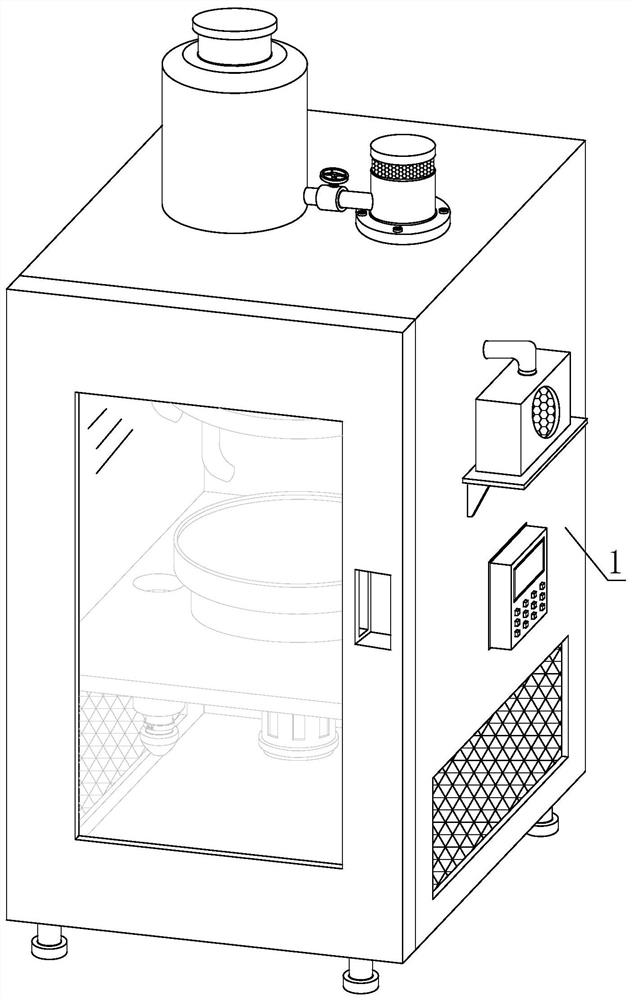
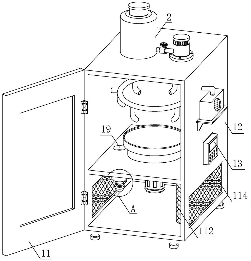
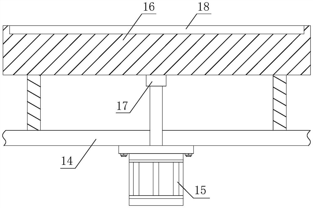
[0031] see Figure 1-3 , a tire cleaning device for new energy vehicles, comprising a cleaning box 1 and a soot blowing device 2, the soot blowing device 2 is arranged in the inner cavity of the cleaning box 1, and the cleaning box 1 includes a door panel 11, a box body 12, a controller 13. Partition plate 14, drive motor 15, storage table 16, fixed sleeve 17 and storage shallow groove 18, one side outer wall of door panel 11 is fixedly connected with the side outer wall of box body 12 port through hinge, and box body 12 A controller 13 is arranged on one side of the outer wall, and the partition 14 is installed between the inner walls of both sides of the box body 12, and the partition 14 and the box body 12 are in an integrated structure, and the bottom of the partition 14 is installed with a drive Motor 15, the drive shaft of drive motor 15 runs through the partition 14 and extends upwards, and the end extends to the inside of the cavity at the bottom of the storage table 1...

Embodiment 2

[0033] see figure 2 , Figure 4 and Figure 5, a tire cleaning device for new energy vehicles, the upper ends of the partitions 14 on both sides of the storage table 16 are respectively provided with ash discharge ports 19, and the outer walls of the partitions 14 at the lower ends of the ash discharge ports 19 are respectively provided with ash discharge pipes 110 , the bottom of the ash discharge pipe 110 is respectively provided with an integrated nozzle 111, the outer wall of the nozzle 111 is sleeved with a filter bag 112, the nozzle 111 is a top-thin and bottom-thick gyro-shaped structure, and the filter bag 112 passes through the elastic belt provided at the port 1121 is socketed and bound on the outer wall of the thin tube of the nozzle 111, and the outer wall of the port of the filter bag 112 is also provided with a hoop mechanism 113 for fixing, and the ash cleaning airflow drives the dust through the ash discharge port 19 and the ash discharge port while blowing t...

Embodiment 3

[0035] see Figure 6-7 , a tire cleaning device for new energy vehicles, the hoop mechanism 113 includes a left half ring 1131, a right half ring 1132, a movable link 1133, a fixed shaft 1134, a swivel ring 1135 and a limit rod 1136, the left half One end of the ring 1131 and the right half ring 1132 is fixedly connected by a movable connector 1133, and a fixed shaft 1134 is fixedly connected to the outer wall of the port at the other end of the left half ring 1131, and a swivel ring 1135 is sleeved on the outer wall of the fixed shaft 1134, and One end of the stop bar 1136 is fixedly connected to one side of the swivel 1135; the outer wall of the port at the other end of the right half ring 1132 is provided with a U-shaped clip 1137, and one end of the U-shaped clip 1137 has a telescopic structure. And on the outer wall of the right half ring 1132 ports corresponding to the end of the other end leg end, limit hole 1138 is offered. The piece 1137 cooperates with the limit hol...


PUM


Abstract

The invention discloses a tire dust removing device used for a new energy automobile, and aims to solve the problems of dust flying and high water consumption in washing caused by outdoor operation ofthe conventional dust removing device. According to the tire dust removing device used for the new energy automobile, a storage table is arranged at the upper end of a partition plate in the inner part of a box body of a cleaning box, a shallow storage groove is formed for storing a tire, an air blower is installed on the outer wall of one side of the box body by using a support, an air outlet barrel of the air blower communicates with an annular pipe between the side walls of the box body at the upper end of the storage table by using an air guide pipe, a spray pipe arranged at the bottom ofthe annular pipe is used for carrying out soot blowing treatment on the tire, a water storage tank is arranged at the top of the box body, the water storage tank communicates with the air guide pipethrough cooperation of a water outlet pipe, a manual control valve, an atomizer and a guide pipe for dust falling treatment, and dust removing is carried out on the tire through atomized water mixed airflow, so that the trouble that dust flies during dust blowing and scatters after a door plate is opened is avoided, water consumption is reduced, workers are prevented from being infringed by the dust, and practicability and reliability are achieved.

Description

technical field [0001] The invention relates to the technical field of cleaning equipment, in particular to a tire cleaning device for new energy vehicles. Background technique [0002] New energy, also known as unconventional energy, refers to various forms of energy other than traditional energy, and refers to energy that has just begun to be developed and utilized or is being actively researched and yet to be promoted, such as solar energy, geothermal energy, wind energy, ocean energy, biomass energy and nuclear fusion energy etc. [0003] When most new energy vehicle tires are sold in the exhibition hall, they are placed for too long, resulting in a large amount of dust on the surface, which affects their appearance, reduces sales, and causes economic losses. Therefore, it is necessary to clean the wheels . However, most of the existing cleaning devices are open-air operations, which are likely to cause dust to fly and affect the health of the staff after inhalation. F...

Claims


Application Information

Patent Timeline
IPC IPC(8): B08B5/02B08B13/00B01D50/00
CPCB08B5/023B08B13/00B01D50/60
Inventor 史书明
Owner 史书明
Why Eureka
Try Eureka