
Gas turbine stator blade and cooling structure thereof

A cooling technology for gas turbines and blades, which is applied to mechanical equipment, engine components, machines/engines, etc., and can solve problems such as the large influence of cooling air consumption on overall machine efficiency, difficulty in arranging cooling structures, and limitations in cooling design

Active Publication Date: 2020-10-23
浙江燃创透平机械有限公司
View PDF3 Cites 3 Cited by
  • Summary
  • Abstract
  • Description
  • Claims
  • Application Information

AI Technical Summary

Problems solved by technology

The cooling air of the low-pressure stage turbine stator blades comes from the air extraction in the middle stage of the compressor. The cooling air consumption of the blades has a great influence on the efficiency of the whole machine, so the cooling design of the blades is often limited by the amount of cooling air.
At the same time, because the high temperature area is concentrated in the leading edge and trailing edge of the blade, and in the trailing edge area of ​​the blade, it is difficult to arrange the cooling structure inside due to the limitation of the blade structure

Method used


Image

  • Gas turbine stator blade and cooling structure thereof
  • Gas turbine stator blade and cooling structure thereof
  • Gas turbine stator blade and cooling structure thereof

Examples


Embodiment Construction

[0051] It should be understood that the specific embodiments described here are only used to explain the present invention, not to limit the present invention.

[0052] Below, the present invention will be further described in detail through specific embodiments in conjunction with the accompanying drawings.

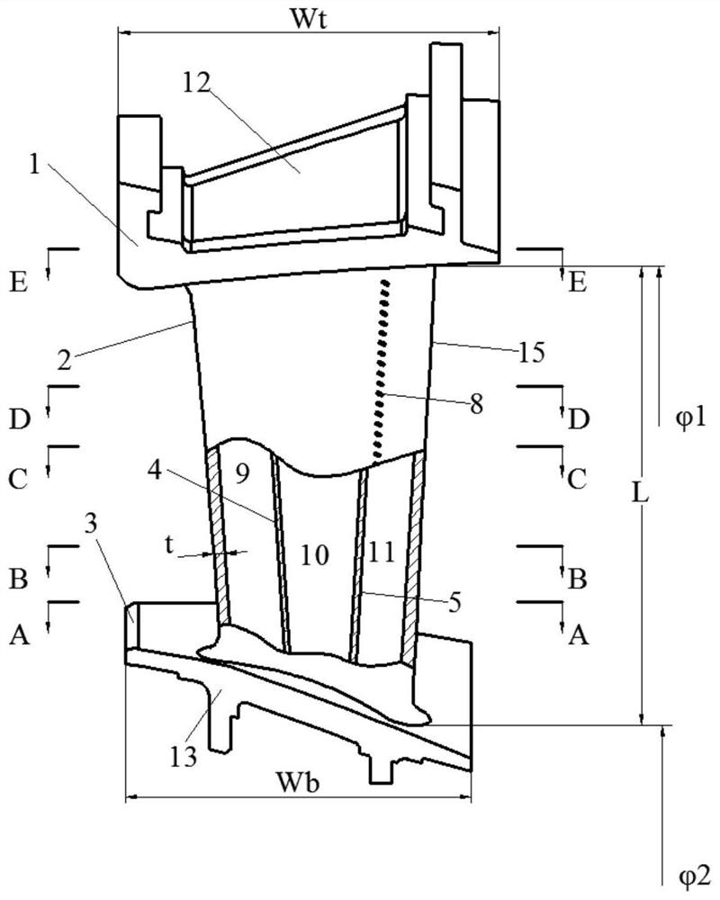
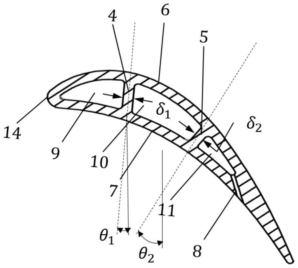
[0053] Such as Figure 1-16 As shown, the present invention provides a blade cooling structure, comprising:

[0054] The first blade partition 4,

[0055] The second blade partition 5 spaced apart from the first blade partition 4,

[0056] The first cooling channel 9 , the second cooling channel 10 and the third cooling channel 11 divided by the first blade separator 4 and the second blade separator 5 ,

[0057] Air film holes 8 communicating with the third cooling channel 11 .

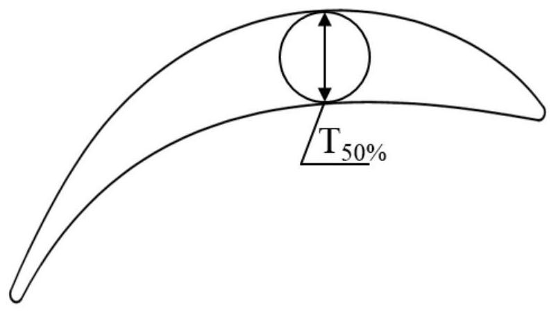
[0058] Preferably, the thickness δ of the first blade separator 4 1 The maximum thickness T of the airfoil section at 50% of the leaf height 50% The ratio range is 0.146-0.178, the draft a...


PUM


Abstract

The invention discloses a gas turbine stator blade and a cooling structure thereof. The cooling structure comprises a first blade partition plate, a second blade partition plate spaced from the firstblade partition plate, a first cooling channel, a second cooling channel, a third cooling channel and an air film hole, wherein the first cooling channel, the second cooling channel and the third cooling channel are partitioned by the first blade partition plate and the second blade partition plate, and the air film hole communicates with the third cooling channel; and the ratio of the thickness delta1 of the first blade partition plate to T50% is 0.146-0.178, the draft angle theta1 ranges from -10 degrees to 10 degrees, the ratio of the thickness delta2 of the second blade partition plate toT50% is 0.146-0.178, and the draft angle theta2 ranges from -10 degrees to 10 degrees. The stator blade comprises an upper edge plate, the blade body and a lower edge plate, and the blade body comprises a blade suction surface, a blade pressure surface, a blade front edge, a blade tail edge and the blade cooling structure. The cooling effect is good, the pneumatic efficiency is high, and the requirements for blade cooling and cascade sealing can be met at the same time under the condition of less cold air.

Description

technical field [0001] The invention relates to the technical field of ground heavy-duty gas turbine blades, and in particular discloses a gas turbine stationary blade with good cooling effect and high aerodynamic efficiency and a cooling structure thereof. Background technique [0002] Gas turbine units are widely used in many fields such as ships and generator sets because of their advantages such as light weight, small size, fast start-up, and convenient control. It can be seen from the simple cycle mode of the gas turbine that the specific power and performance can be improved by increasing the initial temperature of the gas. The position where the turbine blades are located has high temperature, complex stress, and harsh working environment. Therefore, whether the turbine blades can work safely and reliably is very important for the operation of the gas turbine. The performance indicators of blades are also important indicators to measure the development level of gas t...

Claims


Application Information

Patent Timeline
IPC IPC(8): F01D9/04F01D25/12
CPCF01D9/041F01D25/12
Inventor 蓝吉兵隋永枫魏佳明吴宏超王博谢健初鹏周灵敏戴斌余沛坰
Owner 浙江燃创透平机械有限公司
Learn More