Visual sensor optical optimization device and correction method for outdoor complex environment

A visual sensor and complex environment technology, applied in optics, optical components, televisions, etc., can solve problems that affect system measurement reliability, thick protective glass, and inability to disperse in time

Active Publication Date: 2020-10-23
江苏集萃智能光电系统研究所有限公司
View PDF6 Cites 1 Cited by
  • Summary
  • Abstract
  • Description
  • Claims
  • Application Information

AI Technical Summary

Problems solved by technology

[0002] The shell glass part of the traditional visual sensor used in complex outdoor environments is ordinary glass, because the glass plate is a transparent material, when the light hits the glass plate, a small part of the light will be reflected back by the side of the glass plate facing the object Reflection occurs to form a virtual image, and most of the light is not reflected back, but is refracted twice through the glass plate and then into the air, so that the image is darker and unclear
Existing visual sensors are easily affected by complex light from the outside, resulting in low signal-to-noise ratio, which seriously affects the reliability of system measurement
The existing visual sensor glass is ordinary optical glass, which cannot be dissipated in time when it encounters external rain, mist, etc., reducing the imaging quality
At present, manual timely maintenance is often used to ensure the imaging quality of the camera, resulting in high cost and reducing the promotion...

Method used


Image

  • Visual sensor optical optimization device and correction method for outdoor complex environment
  • Visual sensor optical optimization device and correction method for outdoor complex environment
  • Visual sensor optical optimization device and correction method for outdoor complex environment

Examples


Embodiment Construction

[0046] The following will clearly and completely describe the technical solutions in the embodiments of the present invention with reference to the drawings in the embodiments of the present invention.

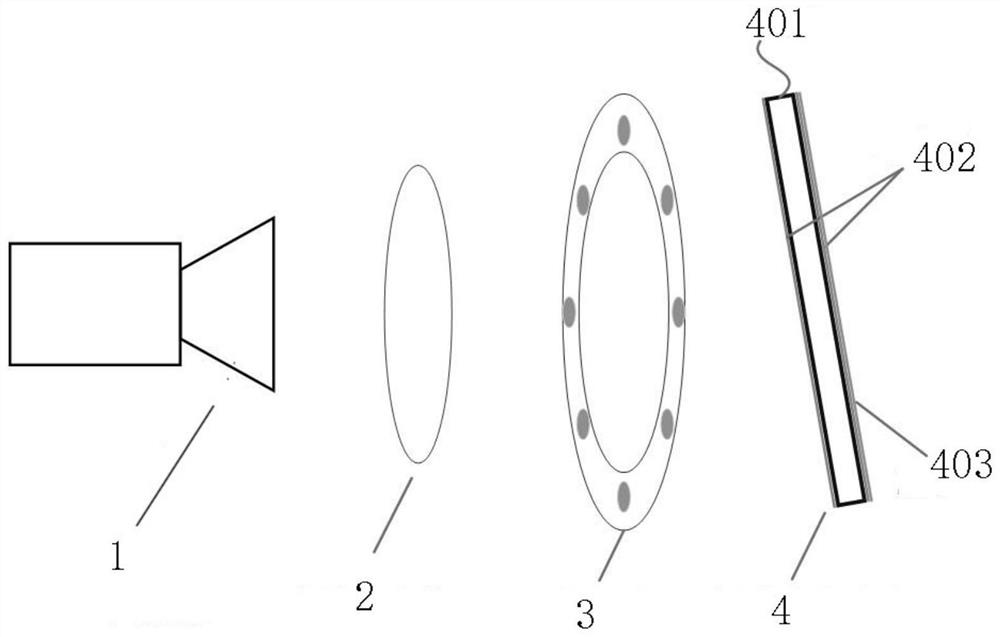
[0047] See figure 1 , a visual sensor optical optimization device for outdoor complex environments of the present invention, which is installed in the housing of the visual sensor, including the front of the camera lens 1 placed in the visual sensor, which is arranged sequentially from the image side to the object side:

[0048] Optical filter 2, in order to shield the outdoor stray light interference and improve the imaging signal-to-noise ratio of the measured target, the optical filter 2 of the visual sensor optical optimization device for outdoor complex environments in this embodiment adopts a near-infrared narrow-band filter The optical filter 2 corresponds to the wavelength of the light source 3. In this embodiment, its wavelength range is 808nm±10nm, which can effectiv...


PUM


Abstract

The invention provides a visual sensor optical optimization device for an outdoor complex environment, which can improve the imaging definition of the visual sensor in an outdoor complex environment,ensures that the measurement precision is not influenced. The device comprises an optical filter, a light source, and protective glass, which are sequentially arranged from an image side to an objectside in front of a camera lens of the vision sensor, wherein the optical filter is a narrow-band optical filter, and the optical filter corresponds to the wavelength of the light source; the light source comprises an annular LED lamp strip which is coaxially arranged with the camera lens; the protective glass comprises optical glass, the two sides of the optical glass are respectively provided with an antireflection film corresponding to the wavelength of the light source, the outer side of the antireflection film close to the object side is provided with a protective film, and the invention also provides a correction method which can be used for correcting the refraction deviation generated on the optical optimization device so as to further ensure the measurement precision.

Description

technical field [0001] The invention relates to the technical field of optical imaging optimization and precision measurement, in particular to an optical optimization device and calibration method for visual sensors used in complex outdoor environments. Background technique [0002] The shell glass part of the traditional visual sensor used in complex outdoor environments is ordinary glass, because the glass plate is a transparent material, when the light hits the glass plate, a small part of the light will be reflected back by the side of the glass plate facing the object Reflection occurs to form a virtual image, and most of the light is not reflected back, but is refracted twice through the glass plate and then into the air, so that the image is relatively dark and unclear. Existing visual sensors are easily affected by complex light from the outside, resulting in low signal-to-noise ratio and seriously affecting the reliability of system measurement. The existing visua...

Claims


Application Information

Patent Timeline
IPC IPC(8): H04N5/225H04N17/00G02B27/00
CPCH04N17/002G02B27/0012H04N23/52H04N23/56H04N23/51H04N23/54H04N23/55
Inventor 黄磊
Owner 江苏集萃智能光电系统研究所有限公司
Why Eureka
Try Eureka