Battery cell blanking clamping mechanism

A clamping mechanism and cell technology, used in circuits, electrical components, secondary batteries, etc., can solve the problems of large circumferential space for rolling needles, easy to drive the inner diaphragm, and small clamping force.

Pending Publication Date: 2020-10-27
GEESUN AUTOMATION TECH
View PDF0 Cites 2 Cited by
  • Summary
  • Abstract
  • Description
  • Claims
  • Application Information

AI Technical Summary

Problems solved by technology

Moreover, the current clamping mechanism for cell blanking has the following problems: 1. The clamping roller is cylindrical, which occupies a large space in the circumferential direction of the needle, and the inner diaphragm pole piece is easy to collapse during the process of cell winding and blanking; 2. The clamping roller Deformation and breakage are prone to occur in the direction of force, causing one end to not be clamped tightly, and the inner side of the cell is easy to wrinkle during pre-pressing; 3. The contact area between the clamping roller and the arc surface of the cell is large, and the clamping force per unit area is small. When the needle is pulled back, it is easy to drive the inner diaphragm, causing the battery core to be scrapped

Method used


Image

  • Battery cell blanking clamping mechanism
  • Battery cell blanking clamping mechanism
  • Battery cell blanking clamping mechanism

Examples


no. 1 example

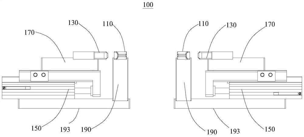
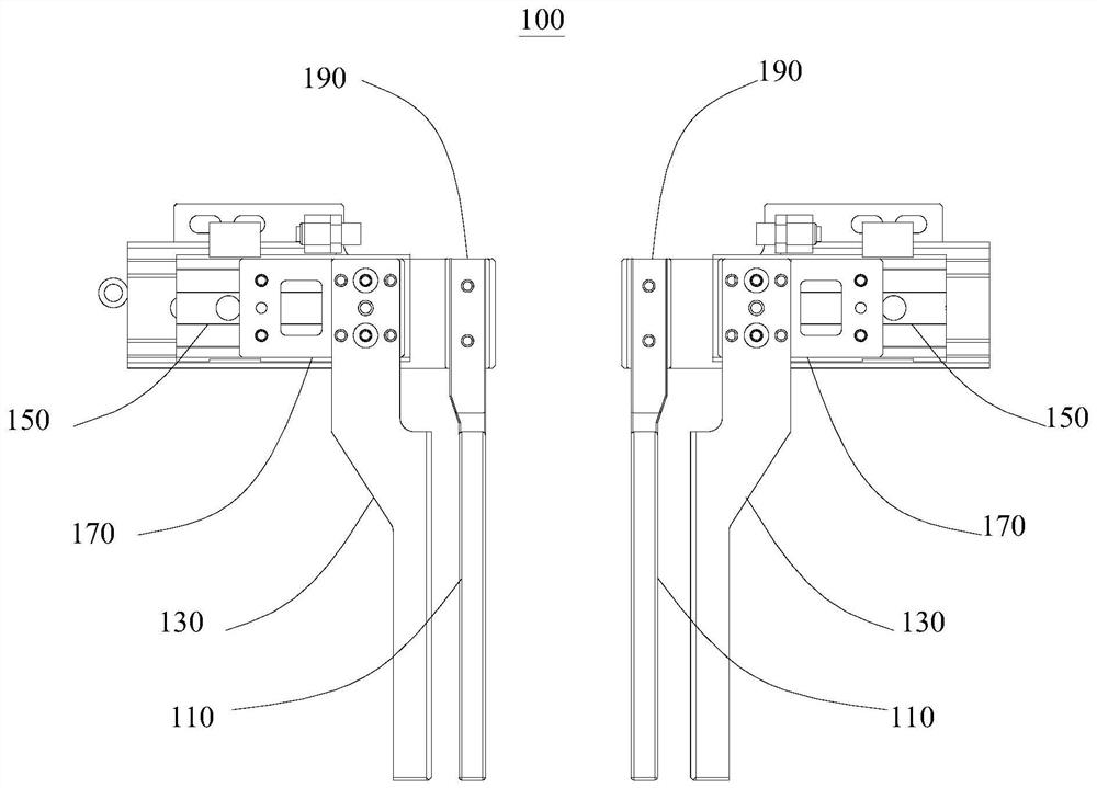
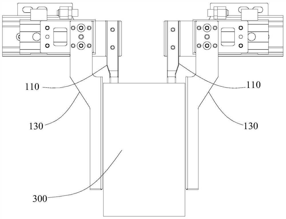
[0034] Join in Figure 1 to Figure 6 , this embodiment provides a cell blanking clamping mechanism 100, which has good clamping effect, is not easily deformed, and occupies a small space, so that the space reserved on the needle winding mechanism 210 is relatively small, so that the cell 300 can be wound. During the cutting process, the inner diaphragm pole piece is not easy to collapse, and the contact area between the clamping roller and the arc surface of the battery cell 300 is relatively small, and the clamping force per unit area is large.

[0035] The cell blanking and clamping mechanism 100 provided by the present invention includes an inner clamping plate 110, an outer clamping plate 130 and a clamping driving mechanism 150. The inner clamping plate 110 and the outer clamping plate 130 are arranged opposite to each other, and the clamping driving mechanism 150 is simultaneously connected with the inner clamping plate 110 and the outer clamping plate 150. The splint 13...

no. 2 example

[0056] see Figure 7 , this embodiment provides a winding device 200, including a needle rolling mechanism 210 and a cell blanking and clamping mechanism 100, wherein the cell blanking and clamping mechanism 100, wherein the basic structure of the cell blanking and clamping mechanism 100 and The principle and the resulting technical effects are the same as those of the first embodiment. For a brief description, for the parts not mentioned in this embodiment, reference may be made to the corresponding content in the first embodiment.

[0057] In this embodiment, the cell blanking and clamping mechanism 100 includes an inner clamping plate 110, an outer clamping plate 130 and a clamping driving mechanism 150. The inner clamping plate 110 and the outer clamping plate 130 are disposed opposite to each other, and the clamping driving mechanism 150 is simultaneously connected with the inner clamping plate 110. It is drivingly connected with the outer clamping plate 130 to drive the ...


PUM


Abstract

The embodiment of the invention provides a battery cell blanking clamping mechanism, and relates to the field of lithium battery manufacturing equipment. The battery cell blanking clamping mechanism comprises an inner side clamping plate, an outer side clamping plate and a clamping driving mechanism, wherein the inner side clamping plate and the outer side clamping plate are oppositely arranged; the clamping driving mechanism is simultaneously in transmission connection with the inner side clamping plate and the outer side clamping plate and is used for driving the inner side clamping plate and the outer side clamping plate to be mutually close to each other or mutually separated; and the cross sections of the inner side clamping plate and the outer side clamping plate are rectangular. Through the adoption of the inner side clamping plate and the outer side clamping plate of rectangular and plate-shaped structures, the occupied space of the clamping plates is smaller; the probability of battery cell inner side collapse is reduced; meanwhile, the clamping plates are more stable when being stressed in the horizontal direction; deformation cannot easily occur, so that the deformationand wrinkling of the battery cell can be avoided; the contact area between the clamping plates and the battery cell is smaller; the clamping force is greater; the clamping effect is good; and the corepulling risk due to driving of an inner layer diaphragm during the needle coiling and needle pulling can be reduced.

Description

technical field [0001] The invention relates to the field of lithium battery manufacturing equipment, in particular, to a blanking and clamping mechanism for battery cells. Background technique [0002] At present, in the production process of power lithium battery, the positive and negative electrode sheets and the separator are mainly formed by the winding machine to form the battery core. After the battery core is wound on the winding needle, the clamping mechanism is usually used to unload; The tightening mechanism usually clamps the cell through the inner and outer pinch rollers, and the winding needle is pulled back to realize the blanking. And the current cell blanking clamping mechanism has the following problems: 1. The clamping roller is cylindrical, which occupies a large space in the circumferential direction of the winding needle, and the inner diaphragm pole piece is easy to collapse during the cell winding and blanking process; 2. The clamping roller It is ea...

Claims


Application Information

Patent Timeline
Patent Type & Authority Applications(China)
IPC IPC(8): B65G47/90H01M10/0587
CPCB65G47/901H01M10/0587Y02E60/10Y02P70/50
Inventor 杨吉晁浩明阳如坤魏宏生陈飞
Owner GEESUN AUTOMATION TECH
Why Eureka
Try Eureka