
Forming system based on semi-solid melt of low melting point alloy

A semi-solid, low-melting point technology, applied in the direction of feeding molten metal into molds, metal processing equipment, manufacturing tools, etc., can solve the problem of uneven composition of semi-solid alloys, poor roundness of crystal nuclei, high preparation costs, etc. problem, achieve the effect of solving the problem of stirring dead zone, stable alloy composition and accelerated fission speed

Active Publication Date: 2021-01-15
浙大宁波理工学院
View PDF4 Cites 0 Cited by
  • Summary
  • Abstract
  • Description
  • Claims
  • Application Information

AI Technical Summary

Problems solved by technology

The existing low-melting point semi-solid alloys need to go through multiple processes in order to prepare the solid alloys into semi-solid alloys. The process is complicated and the degree of automation is low. Moreover, the existing semi-solid alloy preparation devices mostly use mechanical stirring, electromagnetic Stirring and ultrasonic stirring
However, the semi-solid alloy produced by mechanical stirring has disadvantages such as uneven composition and poor roundness of crystal nuclei, and the preparation device is not easy to clean
Electromagnetic stirring and ultrasonic stirring devices still have stirring dead zone, low utilization rate of alloy and high preparation cost
In addition, after the semi-solid alloy is prepared, it needs to be processed and formed, and the forming ability of the semi-solid alloy is far less than that of lead, so the application is very limited.

Method used


Image

  • Forming system based on semi-solid melt of low melting point alloy
  • Forming system based on semi-solid melt of low melting point alloy
  • Forming system based on semi-solid melt of low melting point alloy

Examples


Embodiment Construction

[0024] The present invention is further explained in conjunction with the accompanying drawings.

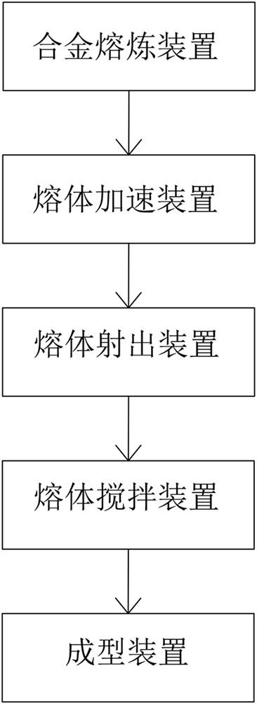
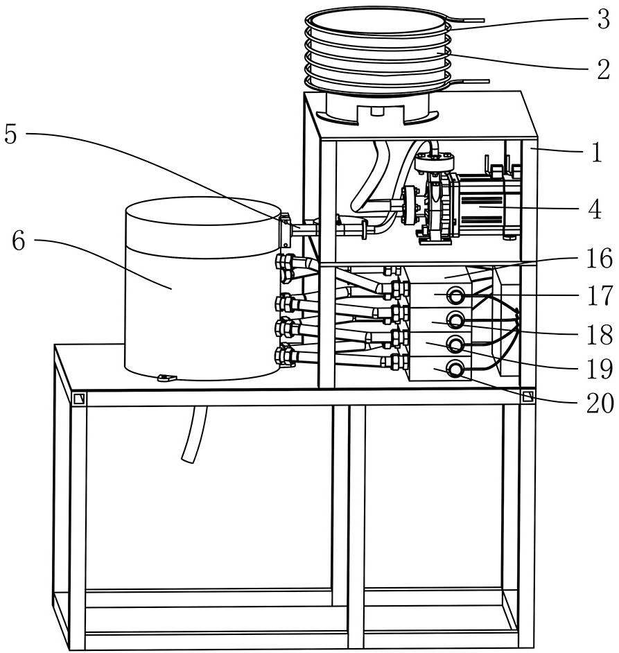
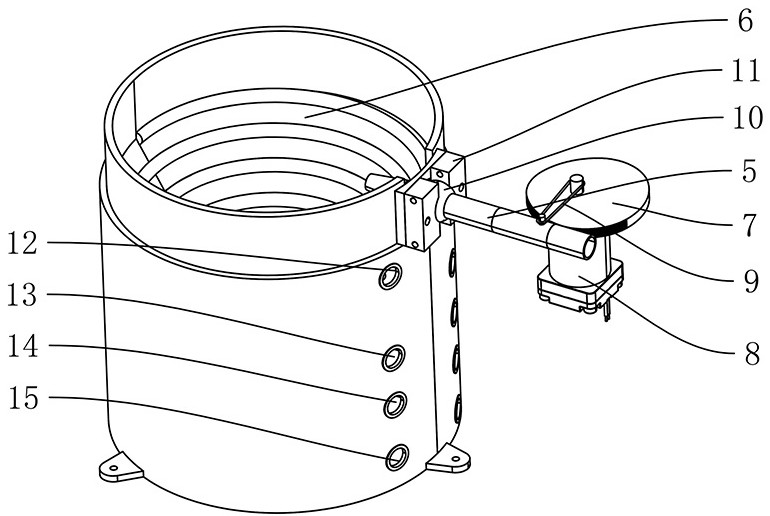
[0025] see Figure 1 to Figure 6 The shown forming system based on low-melting point alloy semi-solid melt includes a preparation device and a forming device, the preparation device includes a frame 1, including a frame 1, and the frame 1 is provided with an alloy melting device, a melt An acceleration device, a melt injection device, and a melt stirring device, the alloy melting device includes a crucible 2 and a heating element 3, the crucible 2 is used to place an alloy, and the heating element 3 heats the crucible 2 so that The alloy in the crucible 2 is smelted to form a semi-solid melt, the crucible 2 is set on the frame 1 through the mounting frame, the heating element 3 is an induction coil, and the induction coil is wound around the outer periphery of the crucible 2. The induction coil is fed with an alternating intermediate frequency current, and the strength of the cu...


PUM


Abstract

The invention discloses a forming system based on a low melting point alloy semi-solid melt, which includes a preparation device and a forming device. The preparation device includes a frame, and the frame is equipped with an alloy melting device, a melt injection device, and a melt stirring device. The alloy smelting device smelts the alloy to form a semi-solid melt, and the melt injection device includes a spray pipe, and the semi-solid melt is ejected from the spray pipe; the melt stirring device includes a stirring chamber; the forming device includes a molding die, and the inside of the molding die is There are a main cavity and a branch cavity, the main cavity and the branch cavity are connected, and the discharge port is connected to the main cavity. There are several cooling channels in the forming mold, and several cooling channels are distributed around the main cavity. The forming mold A plurality of heating channels are arranged along the circumference of the lumen of the branch pipe, and the heating channels are distributed around the lumen of the branch pipe. The invention has high degree of automation, and the composition of the semi-solid alloy is uniform, the roundness of crystal nuclei is good, and the forming effect of the semi-solid alloy is good.

Description

technical field [0001] The invention relates to the technical field of rheological forming, in particular to a forming system based on semi-solid melt of low melting point alloy. Background technique [0002] Semi-solid alloy is a kind of "soft matter" between liquid and solid. It can be transported like a solid when it is still, and can be continuously deformed like a fluid under the action of an external force. Its internal feature is that (near) spherical crystals are uniformly suspended in the liquid. in phase. [0003] Environmentally friendly low-melting point alloys can be used to prepare semi-solid metals, and low-melting point alloys can undergo liquid-solid phase transitions within 100°C. The existing low-melting point semi-solid alloys need to go through multiple processes in order to prepare the solid alloys into semi-solid alloys. The process is complicated and the degree of automation is low. Moreover, the existing semi-solid alloy preparation devices mostly u...

Claims


Application Information

Patent Timeline
Patent Type & Authority Patents(China)
IPC IPC(8): C22C1/00B22D35/06B22D35/04
CPCB22D35/06B22D35/04C22C1/12
Inventor 刘文潘哲豪张海英王春鸽张池邬炎栩于艳东何桢泓应祺辉
Owner 浙大宁波理工学院
Learn More