
Textile printing and dyeing device based on high-energy microbubble technology

A technology for textiles and microbubbles, which is applied in the configuration of equipment for processing textile materials, spraying/jetting textile materials, etc., and can solve problems such as a large amount of waste water, blockage, and environmental problems.

Inactive Publication Date: 2020-10-27
王海燕
View PDF0 Cites 0 Cited by
  • Summary
  • Abstract
  • Description
  • Claims
  • Application Information

AI Technical Summary

Problems solved by technology

Its disadvantage is that the dripper is easy to scale and block, so the water source should be strictly filtered
The dyeing method of repeatedly immersing the textile in the dyeing solution to make it move relative to the dyeing solution is widely used in the textile printing and dyeing industry because of its simple operation and low cost, and has become the most common and basic method of textile printing and dyeing. However, in the process of dip-dyeing, a large amount of dyes and water resources need to be used. For some areas where water resources are scarce, cotton thread is restrictive. At the same time, a large amount of wastewater will be generated in the process of dip-dyeing. The direct discharge of these wastewater will induce serious environmental problems. , and the construction of corresponding sewage treatment equipment will also greatly increase the cost of dip-dyeing technology

Method used


Image

  • Textile printing and dyeing device based on high-energy microbubble technology
  • Textile printing and dyeing device based on high-energy microbubble technology
  • Textile printing and dyeing device based on high-energy microbubble technology

Examples


Embodiment 1

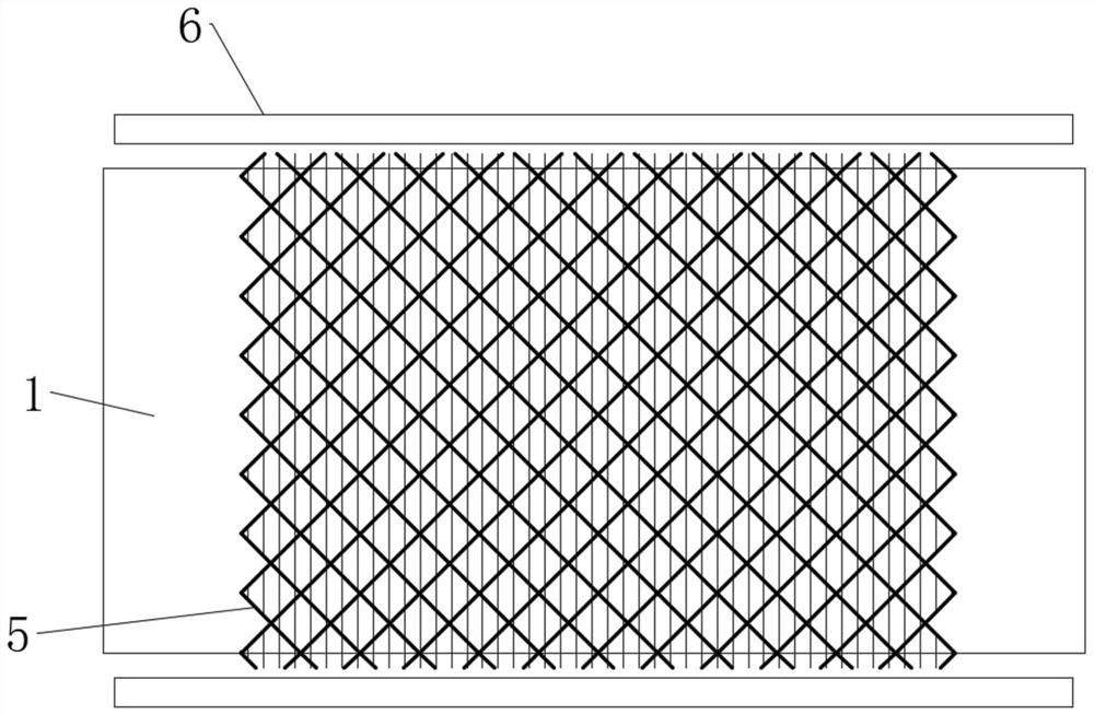
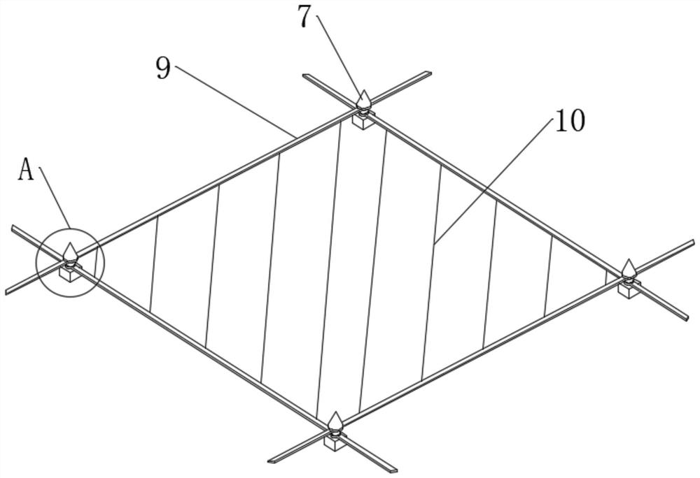
[0037] see Figure 1-2 , a textile printing and dyeing device based on high-energy microbubble technology, including a textile main body 1 and a driving roller 2, and the textile main body 1 is installed on the driving roller 2, and the textile main body 1 is always in a tensioned state, and the upper side of the textile main body 1 is set There is a nozzle frame 3, and one end of the nozzle frame 3 close to the textile body 1 is fixedly connected with a plurality of uniformly distributed high-energy microbubble nozzles 4, and the upper side of the textile body 1 is provided with a telescopic belt 5, which is located between the textile body 1 and the nozzle frame. between 3.

[0038] Among them, the driving roller 2, the nozzle frame 3 and the telescopic belt 5 of the rice in the present application are all fixedly connected to the frame respectively, and the fixed connection is realized through the frame, while the high-energy microbubble nozzle 4 is connected with the dye s...


PUM


Abstract

The invention discloses a textile printing and dyeing device based on a high-energy microbubble technology, and belongs to the field of textile printing and dyeing devices. For the textile printing and dyeing device based on the high-energy microbubble technology, according to the technical scheme, a technology similar to drip irrigation is utilized, the amount of dye liquor is reduced, the dye liquor is converted into high-energy microbubbles, dye liquid drops forming the high-energy microbubbles are enabled to splash around by instantaneous impact generated by explosion of the high-energy microbubbles, then the dye liquid drops uniformly spread on the surface of a textile main body, macroscopically, uniform printing and dyeing of the whole textile main body are realized through the continuously sprayed high-energy microbubbles, the explosion height of the high-energy microbubbles is controlled by utilizing a telescopic belt, so that the range of splashing of the dye liquid drops of the high-energy microbubbles is wider, then the printing and dyeing efficiency is improved, a large amount of dye liquor does not need to be prepared in advance, then the water consumption in the textile printing and dyeing process can be greatly reduced, the utilization efficiency of water resources and dye is improved, meanwhile, the production rate of wastewater in the production process is reduced, and thus the wastewater treatment cost in the printing and dyeing process is reduced.

Description

technical field [0001] The invention relates to the field of textile printing and dyeing devices, in particular to a textile printing and dyeing device based on high-energy microbubble technology. Background technique [0002] Textiles are products made of textile fibers through processing and weaving. They are divided into two categories: woven fabrics and knitted fabrics. As early as in the farming era, various civilizations developed textiles that met their own conditions according to local conditions, such as flax, cotton and mulberry. Silkworms, etc., and with the use of textiles, the printing and dyeing technology of textiles has gradually been developed and applied to the daily production of textiles. [0003] Printing and dyeing is also called dyeing and finishing. It is a processing method and a general term for pretreatment, dyeing, printing, finishing, washing, etc. In the agricultural era, dyes used for printing and dyeing were mostly natural extracts, mostly pla...

Claims


Application Information

Patent Timeline
Patent Type & Authority Applications(China)
IPC IPC(8): D06B1/02D06B23/20
CPCD06B1/02D06B23/20
Inventor 王海燕
Owner 王海燕
Learn More