
Wire feeding mechanism of steel bar binding machine and steel bar binding machine

A technology of wire feeding mechanism and bundling machine, which is applied in building construction, building material processing, construction, etc., can solve the problems of unstable looping drift, looping failure, and inability to realize automation stably and effectively.

Pending Publication Date: 2020-10-27
GUANGDONG SHUNDE HUAYAN ELECTRONICS TECH CO LTD
View PDF0 Cites 0 Cited by
  • Summary
  • Abstract
  • Description
  • Claims
  • Application Information

AI Technical Summary

Problems solved by technology

The addition of an auxiliary pay-off device will cause inconsistency between the iron wire released by the auxiliary pay-off device and the iron wire sent by the wire feeding mechanism of the steel bar binding machine. It becomes very uncompact and takes up a lot of space, which violates the principle that the strapping machine needs to be compact and compact in the automatic production line
[0006] 2. Or the wire feeding mechanism can drive the wire reel, but because the wire feeding mechanism cannot stably draw out the wire from the large wire reel, the wire of the steel bar binding machine fails to form a loop during the loop forming process. Loop drift instability and other phenomena cause the success rate of the use of the steel bar binding machine is not high, the use is unstable, and it is impossible to realize automation stably and effectively
[0007] 3. Or the wire feeding mechanism can drive the wire reel, that is, the wire feeding mechanism has enough ability to draw the wire out of the large wire reel, and the coiling of the steel bar binding machine is relatively stable, but due to the wire feeding mechanism, the wire feeding wheel If the clamping force of the component is too large, it may easily cause damage to the wire, thinning or other defects. After the steel bar binding machine is looped, when tightening, the maximum tightness that the damaged wire can bind to the steel bar will be reduced. If the binding force is too high, it will easily cause the wire to break. If the torque is reduced, the twist will not be tight, and the binding will fail.

Method used


Image

  • Wire feeding mechanism of steel bar binding machine and steel bar binding machine
  • Wire feeding mechanism of steel bar binding machine and steel bar binding machine
  • Wire feeding mechanism of steel bar binding machine and steel bar binding machine

Examples


Embodiment 1

[0045] A wire feeding mechanism of a steel bar binding machine in this embodiment, such as Figure 6-8 As shown, the wire feeding mechanism includes a transmission mechanism and two groups of wire feeding wheels arranged along the feeding direction of the wire binding. Each group of wire feeding wheels jointly clamps the binding wire and transmits it. The wire wheel and a driven wire feed wheel, when the same group of active wire feed wheels and driven wire feed wheels are meshed, they form a conveying groove that can bite and transmit the wire, and the transmission mechanism drives the active wire feed wheels of each group of wire feed wheels to rotate synchronously .

[0046] The wire feeding mechanism of the steel bar binding machine in this embodiment is used for the single wire transmission of large rolls of wires in automation equipment, that is, two groups of wire feeding wheels jointly convey one wire.

[0047]Specifically, the wire feed rollers of the wire feed mecha...

Embodiment 2

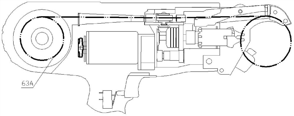
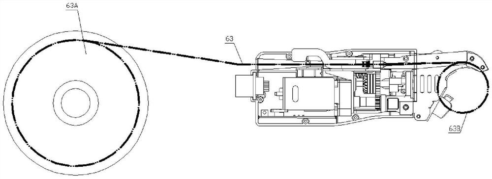
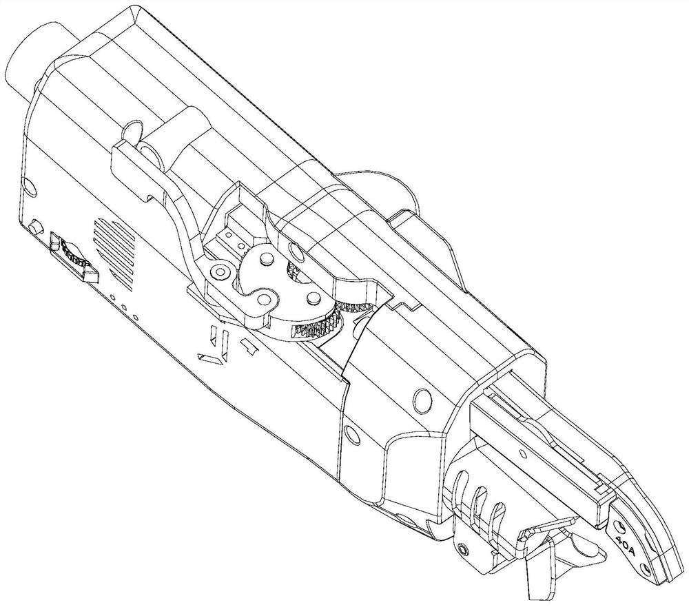
[0057] This embodiment is a steel bar binding machine, comprising the wire feeding mechanism of the steel bar binding machine described in Embodiment 1. The wire feeding mechanism of the steel bar binding machine is installed on the main body. Such as Figure 2-7 As shown, it is a schematic diagram of the steel bar binding machine of the present invention used in automation equipment to use a large-volume binding coil. The binding wire of the large-volume binding coil 63A is wound in a wire reel, and finally passes through the wire feeding mechanism of the steel bar binding machine to bind the steel bar. The binding region of the machine forms the wire binding circle 63B of the binding steel bar. Depend on figure 1 with figure 2 It can be seen that the steel bar binding machine used by the automation equipment and the large coil wire coil used therein are very different from the existing steel bar binding machine and its application.

Embodiment 3

[0059] This embodiment is a wire feeding mechanism of a steel bar binding machine. Compared with Embodiment 1, the difference is that in this embodiment, two sets of wire feeding wheels simultaneously transmit two wires paralleled horizontally or vertically. That is to say, two groups of wire feeding wheels are arranged in the direction orthogonal to the wire binding conveying direction, and convey the two wire bindings paralleled horizontally or vertically.

[0060] Such as Figure 11a As shown, each group of wire feed wheels occludes and conveys the horizontally juxtaposed binding wires 63, and the cross-sectional shape of the transmission groove coincides with the arrangement of the binding wires, as shown in Figure 11b As shown, each set of wire feed wheels bites and conveys the vertically juxtaposed binding wires 63 , and the cross-sectional shape of the transmission groove matches the arrangement of the binding wires. Therefore, each group of wire feeding wheels can po...


PUM


Abstract

The invention discloses a wire feeding mechanism of a steel bar binding machine. The wire feeding mechanism comprises a transmission mechanism and at least two groups of wire feeding wheels which arearranged along the binding wire feeding direction, wherein each group of wire feeding wheels commonly clamp and convey binding wires, each group of wire feeding wheels comprises a driving wire feedingwheel and a driven wire feeding wheel which are meshed with each other, a conveying groove capable of engaging and conveying the binding wires is formed when the driving wire feeding wheel and the driven wire feeding wheel in the same group are meshed, and the transmission mechanism drives the driving wire feeding wheels of the wire feeding wheels in different groups to synchronously rotate. Thewire feeding mechanism of the steel bar binding machine is provided with at least two pairs of wire feeding wheels which are used for clamping and conveying the binding wires together, so that the capacity of transmitting the binding wires of the wire feeding mechanism is improved, meanwhile, the compression stress to the binding wires of each pair of wire feeding wheels can be reduced by adoptingthe multiple pairs of wire feeding wheels, the binding wires cannot be damaged, and continuous and stable work of the steel bar binding machine on automatic equipment is realized by adopting large coil binding wires.

Description

technical field [0001] The invention relates to the technical field of binding machines, in particular to a wire feeding mechanism of a steel bar binding machine and a steel bar binding machine. Background technique [0002] Existing electric hand-held steel bar binding machines need to consume consumables, i.e. wire coils, during use. The wire coil is placed inside the electric hand-held steel bar binding machine, such as figure 1 As shown, considering the feasibility of manual operation and the limitation of the structural capacity of the steel bar binding machine, the wire used is a wire coil wound into a small roll, and the wire coil is relatively small, such as only 100 wire coils per roll. rice. [0003] With the general promotion and gradual deepening of prefabricated buildings, there are further requirements for the intelligence of prefabricated construction factories, and the automation of the production of prefabricated construction parts will be imminent. The a...

Claims


Application Information

Patent Timeline
Patent Type & Authority Applications(China)
IPC IPC(8): E04G21/12
CPCE04G21/123
Inventor 罗泳杨李移清吴加元肖秀南
Owner GUANGDONG SHUNDE HUAYAN ELECTRONICS TECH CO LTD
Learn More