
Under-screen fingerprint identification module, under-screen fingerprint identification method and electronic equipment

A fingerprint recognition module and fingerprint recognition technology, applied in the optical field, can solve the problems of appearance, affecting the recognition accuracy, and the light signal being easily reflected on the display screen.

Pending Publication Date: 2020-10-27
江西微瑞光学有限公司
View PDF0 Cites 1 Cited by
  • Summary
  • Abstract
  • Description
  • Claims
  • Application Information

AI Technical Summary

Problems solved by technology

[0004] Due to the need to set a light leakage area under the display screen, some non-signal light, that is, stray light, can also reach the sensor chip, which will affect the image clarity and imaging quality, thereby affecting the accuracy of recognition
In addition, the light signal leaked from the light leakage area of ​​the screen is also easily reflected to the display screen, causing appearance problems

Method used


Image

  • Under-screen fingerprint identification module, under-screen fingerprint identification method and electronic equipment
  • Under-screen fingerprint identification module, under-screen fingerprint identification method and electronic equipment
  • Under-screen fingerprint identification module, under-screen fingerprint identification method and electronic equipment

Examples


Embodiment Construction

[0067] In the following, only some exemplary embodiments are briefly described. As those skilled in the art would realize, the described embodiments may be modified in various different ways, all without departing from the spirit or scope of the present invention. Accordingly, the drawings and descriptions are to be regarded as illustrative in nature and not restrictive.

[0068] In describing the present invention, it is to be understood that the terms "center", "longitudinal", "transverse", "length", "width", "thickness", "upper", "lower", "front", " Back", "Left", "Right", "Vertical", "Horizontal", "Top", "Bottom", "Inner", "Outer", "Clockwise", "Counterclockwise", etc. or The positional relationship is based on the orientation or positional relationship shown in the drawings, which is only for the convenience of describing the present invention and simplifying the description, rather than indicating or implying that the referred device or element must have a specific orie...


PUM


Abstract

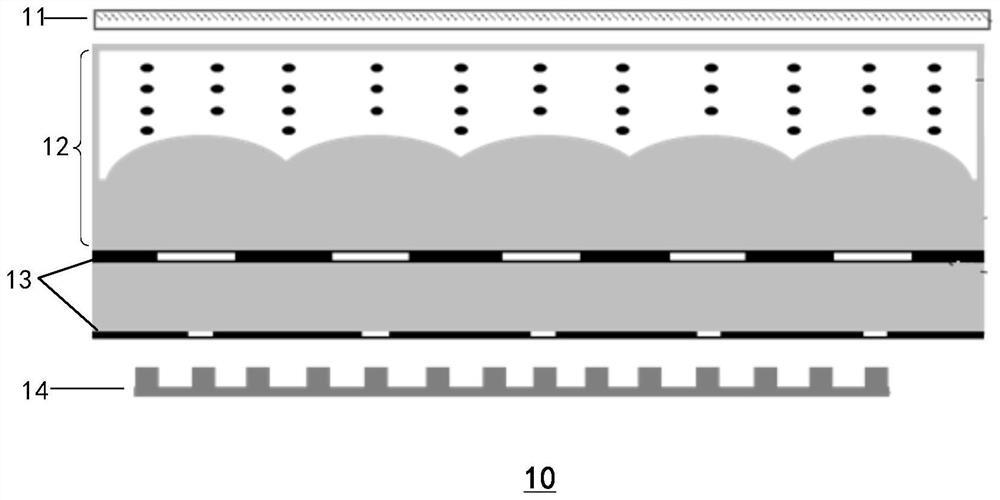
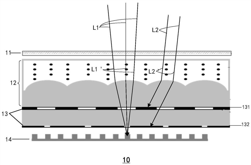
The invention provides an under-screen fingerprint recognition module. The under-screen fingerprint recognition module sequentially comprises a quarter-wave plate, a polarization bifocal microlens array, alight blocking layer, and a photoelectric sensor. The polarization bifocal microlens array is configured to diverge incident light polarized along a first direction or propagate the incident light along an original light path, and focus the incident light polarized along a second direction, wherein the first direction is perpendicular to the second direction; the light blocking layer is configured to allow a portion of the incident light to pass therethrough; and the photoelectric sensor is configured to receive part of incident light passing through the light blocking layer and convert the incident light into an electric signal.

Description

technical field [0001] The present invention generally relates to the field of optical technology, and in particular to an under-screen fingerprint recognition module including a polarized bifocal microlens array, a method for under-screen fingerprint recognition, and an electronic device including the under-screen fingerprint recognition module. Background technique [0002] As electronic devices enter the era of full screens, the biometric collection area on the front of electronic devices is squeezed by the full screen, so the under-display or in-display biometric technology has attracted more and more attention. The technology has solved the problem that the full screen is not comprehensive enough. [0003] The current under-screen fingerprint recognition technology is to install the fingerprint recognition module under the display screen, and set a light leakage area under the display screen. The fingerprint recognition module realizes the under-screen fingerprint recog...

Claims


Application Information

Patent Timeline
IPC IPC(8): G06K9/00G06K9/20G02B3/00
CPCG02B3/0006G06V40/1324G06V10/147
Inventor 梅晶晶王天寅梁乾亿
Owner 江西微瑞光学有限公司
Learn More