Gantry synchronous control method, motor driver and motor control system
A motor driver and synchronous control technology, applied in the direction of multiple motor speed adjustment, etc., can solve the problems of high use cost and maintenance cost, complicated wiring and poor reliability.
- Summary
- Abstract
- Description
- Claims
- Application Information
AI Technical Summary
Problems solved by technology
Method used
Image

Examples
Embodiment 1
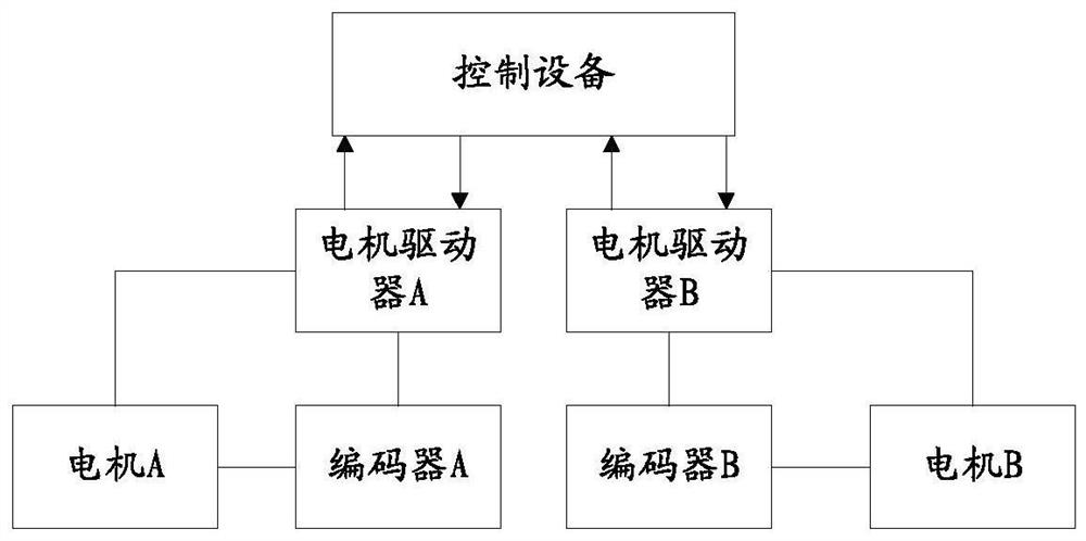
[0078] Aiming at the problems of complex wiring, poor reliability, and high cost of use and maintenance in the gantry control implementation, this embodiment provides a new motor control system for realizing synchronous operation control of at least two motors. For ease of understanding, this embodiment will be described below by taking a motor control system including two motors as an example. However, it should be understood that the motor control system in this embodiment is not limited to controlling the synchronous operation of two motors, and the control of synchronous operation of three or more motors can be deduced by analogy, which will not be repeated here.
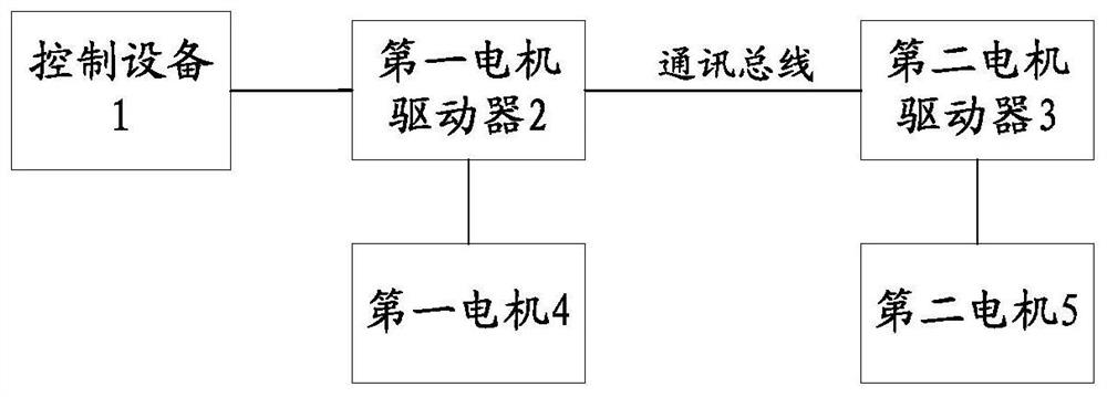
[0079] For the motor control system provided in this embodiment, please refer to figure 2 As shown, it includes a control device 1, a first motor driver 2, a first motor 4, a second motor driver 3 and a second motor 5; wherein the first motor driver 2 communicates with the control device 1, and the first motor ...
Embodiment 2
[0097] For ease of understanding, this embodiment will illustrate the structure of the motor driver based on the above embodiments.
[0098] See image 3 As shown, in this embodiment, the first motor driver 2 includes a first bus communication module 21 and a first gantry controller 22, and the first bus communication module 21 communicates with the second bus communication module of the second motor driver 3 through the communication bus. connect. The first bus communication module 21 in this embodiment can be but not limited to any one of the following bus communication modules: RS485 bus communication module, CAN bus communication module, Ethernet bus communication module. The first bus communication module 21 is used for receiving the second position information sent by the second motor driver 3 through the second bus communication module, the second position information is the position information of the second motor driven and controlled by the second motor driver, and ...
Embodiment 3
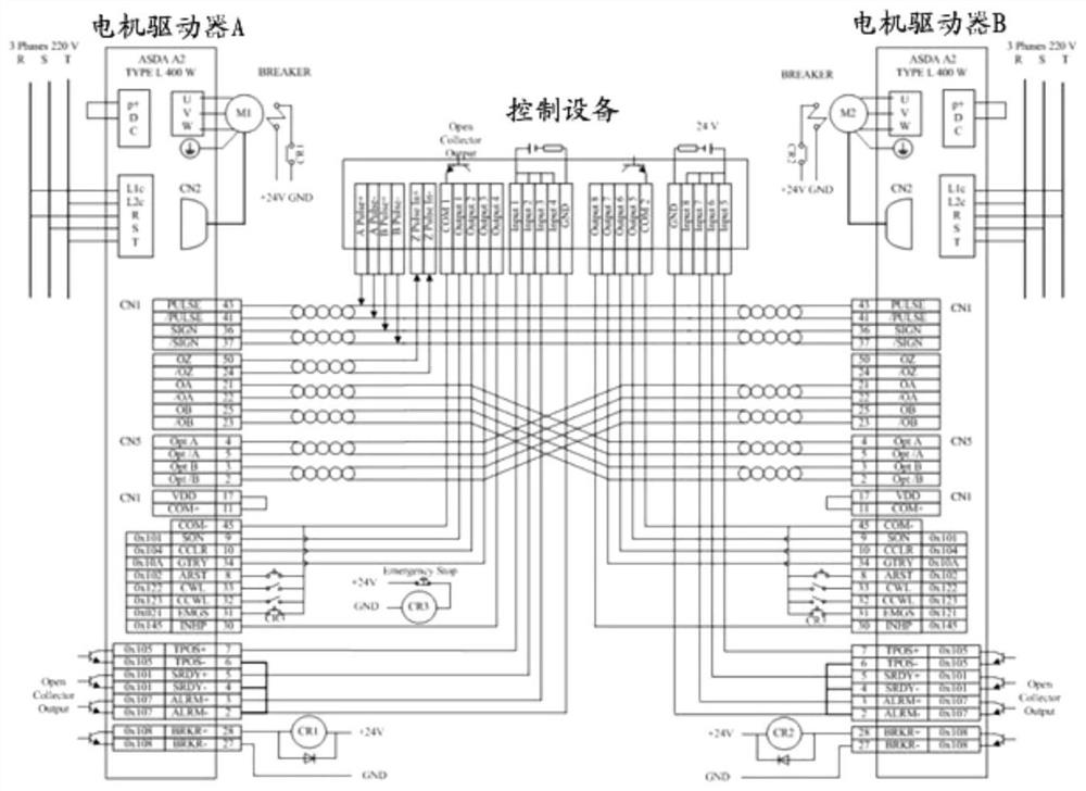
[0111] In order to facilitate understanding, this embodiment applies the following on the basis of the above embodiments figure 2 The motor control system shown and the image 3 and Figure 4 The motor driver shown is an example and one wiring to a motor control system is an example. See Figure 5 As shown, the pulse output terminal of the control device 1 is connected to the pulse input terminals of the first motor driver 2 and the second motor driver 3, and the first motor driver 2 and the second motor driver 3 are connected through the RS485 communication bus. The motor driver 3 sends the real-time position information of the second motor 5 obtained by it to the first motor driver 2 through the RS485 communication interface, and the second motor driver 3 sends the second origin signal triggered by the second motor 5 when it reaches the second origin. Send it to the first motor driver 2 through the RS485 communication bus. After receiving the first origin signal and the s...
PUM
 Abstract
Description
Claims
Application Information
 - R&D
- Intellectual Property
- Life Sciences
- Materials
- Tech Scout
- Unparalleled Data Quality
- Higher Quality Content
- 60% Fewer Hallucinations
Browse by: Latest US Patents, China's latest patents, Technical Efficacy Thesaurus, Application Domain, Technology Topic, Popular Technical Reports.
© 2025 PatSnap. All rights reserved.Legal|Privacy policy|Modern Slavery Act Transparency Statement|Sitemap|About US| Contact US: help@patsnap.com