
Electronic part machining machine

A technology for electronic parts and processing machines, applied in electrical components, circuits, conveyor objects, etc., can solve the problems of increased cost, difficult quality control, large use, and occupation of factory area.

Pending Publication Date: 2020-10-30
吴江市永健达金属制品有限公司
View PDF0 Cites 1 Cited by
  • Summary
  • Abstract
  • Description
  • Claims
  • Application Information

AI Technical Summary

Problems solved by technology

[0003] In the production line of most factories, this kind of processing process is still carried out manually. If you want to catch up with the assembly line operation, you need to use a lot of manpower, which will increase the cost and make quality control difficult. Therefore, the general production line configuration has a processing shift system to carry out this process. It needs 7 to 10 operators to process, and because of a large amount of manpower, it takes up valuable factory area;

Method used


Image

  • Electronic part machining machine
  • Electronic part machining machine
  • Electronic part machining machine

Examples


Embodiment Construction

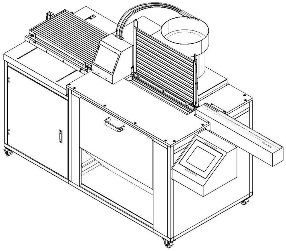
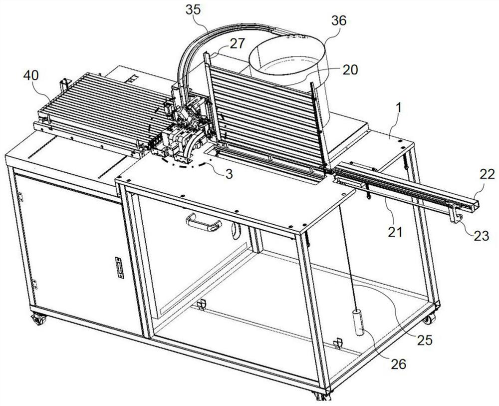
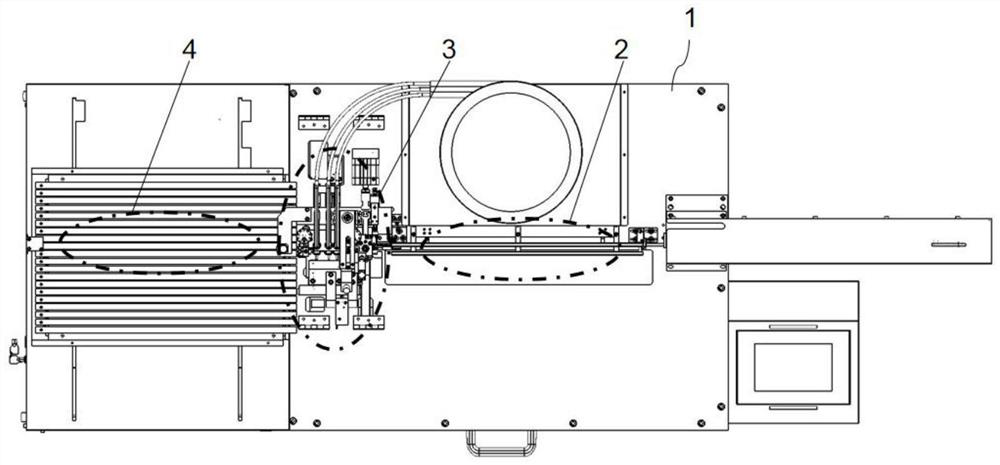
[0033] Such as Figure 1 to Figure 9 As shown, an electronic parts processing machine includes a base surface 1 and a plurality of components 5, and the base surface 1 is provided with a feeding mechanism 2, a processing mechanism 3 and a receiving mechanism 4 in sequence; the feeding mechanism 2 includes several strip-shaped hollow Feed pipe 20, the cross section of feed pipe 20 is the same as the cross section of element 5, elements 5 are arranged in the feed pipe 20 in sequence, and the feed pipe 20 is stacked up and down successively; the two ends of the feed pipe 20 are provided with feeding Pipe guide rail 27, the lower end of feed pipe guide rail 27 joins with base surface 1; The inboard of feed pipe guide rail 27 is provided with slide groove along vertical direction, and the two ends of feed pipe 5 are embedded in the slide groove, and feed pipe 5 can reciprocate up and down; the base surface 1 is also provided with a guiding block, the upper surface of the guiding bl...


PUM


Abstract

The invention provides an electronic part machining machine, and particularly relates to the field of mechanical automation devices. Elements are sequentially arranged in a feeding pipe; the lower endof a feeding pipe guide rail is connected with a base surface; the two ends of the feeding pipe are embedded into sliding grooves, and the feeding pipe can move up and down in a reciprocating mode; one end of a guide groove is connected with one end of the feeding pipe, and the lower ends of the elements are located in the guide groove; a material receiving mechanism comprises a plurality of material receiving pipes, the material receiving pipes are sequentially stacked in the horizontal direction, the cross sections of the material receiving pipes are identical to the cross sections of the elements, and the ends of the material receiving pipes are connected with the other end of the guide groove; a shearing mechanism comprises a cutter cylinder, the cutter cylinder is arranged on the base surface, and a cutter is arranged at the end part of an ejector rod of the cutter cylinder; a cutting board matched with the cutter is arranged on a base plate; a glue dispensing mechanism is provided with a glue dispensing head, and the glue dispensing head can move up and down; the feeding pipe is arranged on the side face of a vibration disc and extends to the position above the elements; andan ejector rod of an air cylinder is inserted into the feeding pipe. According to the electronic part machining machine, the production efficiency can be improved, and the production cost can be reduced.

Description

technical field [0001] The invention belongs to the field of mechanical automation devices, and in particular relates to an electronic parts processing machine. Background technique [0002] In power adapters and related electronics industries, semiconductors and other integrated circuit parts are used. For specific shapes, please refer to the attached drawings. TO220 packaging is generally used. The existing packaging process is as follows: First, cut the metal legs of the parts to the required length, and then cut them to the required length. Put the EMI magnetic ring (bead) on the foot, and then use synthetic resin such as white glue or green glue to glue and fix the two; [0003] In the production line of most factories, this kind of processing process is still carried out manually. If you want to catch up with the assembly line operation, you need to use a lot of manpower, which will increase the cost and make quality control difficult. Therefore, the general production...

Claims


Application Information

Patent Timeline
Patent Type & Authority Applications(China)
IPC IPC(8): B05C5/02B21F11/00B65G47/14H01L21/67
CPCB05C5/0212B21F11/00B65G47/1407H01L21/67121
Inventor 黄国群洪健瑜
Owner 吴江市永健达金属制品有限公司
Learn More