
Auxiliary device for manufacturing direct-current motor controller shell and manufacturing method thereof

A technology of DC motors and auxiliary devices, applied in auxiliary devices, manufacturing tools, auxiliary welding equipment, etc., can solve problems such as welding position and angle deviation, affecting installation, etc., to ensure stability, ensure structural stability, and be convenient and simple to use Effect

Pending Publication Date: 2020-10-30
嵊州市三吉电子有限公司
View PDF12 Cites 0 Cited by
  • Summary
  • Abstract
  • Description
  • Claims
  • Application Information

AI Technical Summary

Problems solved by technology

The mounting plate and the shell are generally fixed by welding, and in order to ensure the firmness of the installation between the controller and the mounting cavity, the welding angle and position of the mounting plate and the shell need to be determined according to the actual installation requirements, while the prior art There is no auxiliary device for the welding between the mounting plate and the shell, so that there is a certain deviation in the welding position and angle between the mounting plate and the shell, which affects the actual installation

Method used


Image

  • Auxiliary device for manufacturing direct-current motor controller shell and manufacturing method thereof
  • Auxiliary device for manufacturing direct-current motor controller shell and manufacturing method thereof
  • Auxiliary device for manufacturing direct-current motor controller shell and manufacturing method thereof

Examples


Embodiment Construction

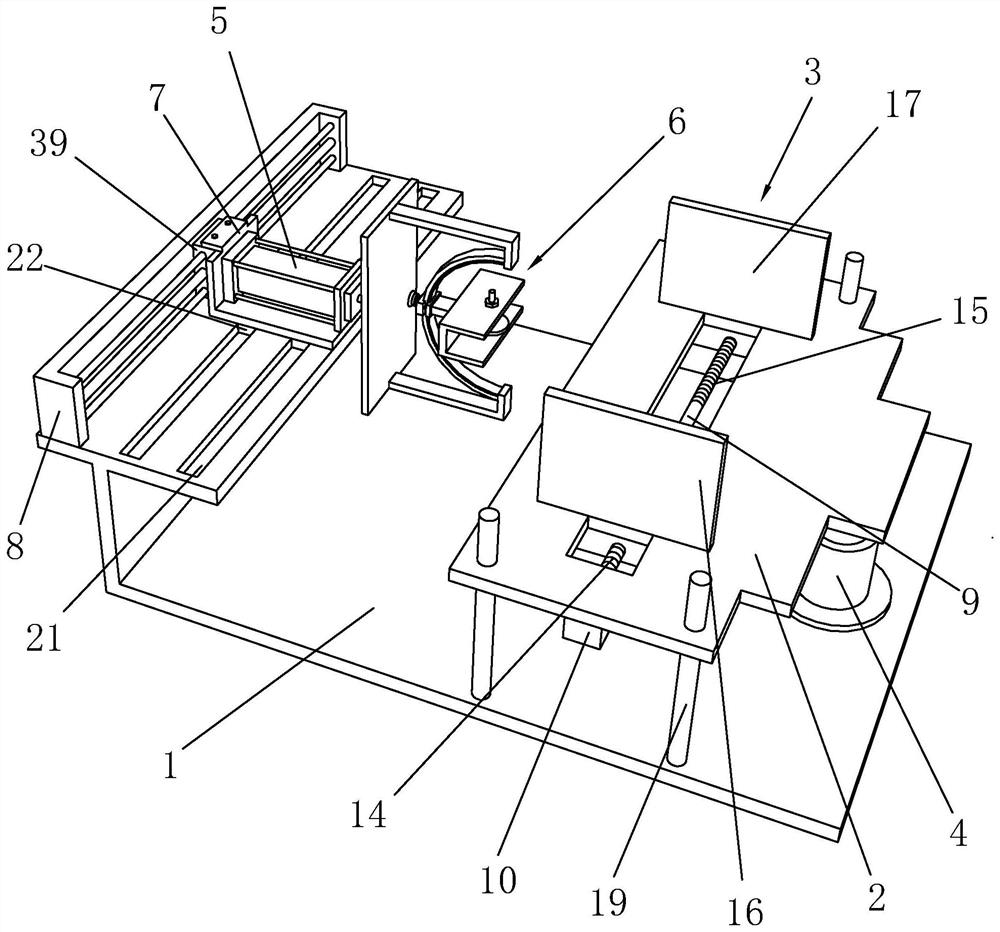
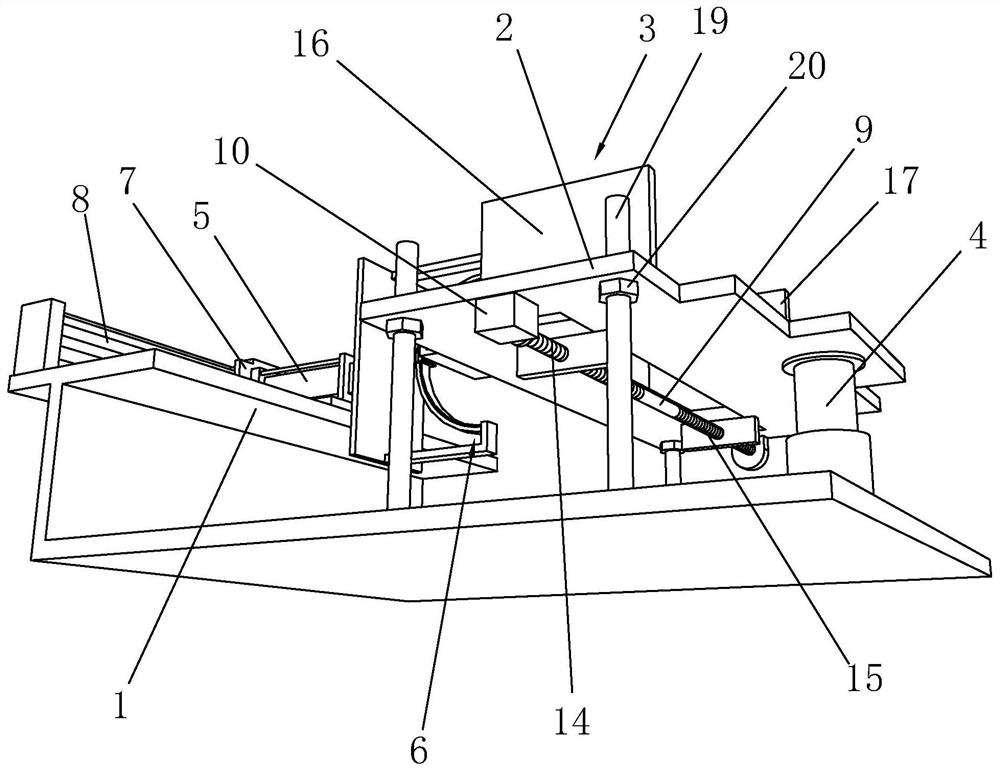
[0045] Such as Figure 1 to Figure 8 As shown, it is an auxiliary device for the manufacture of a DC motor controller housing of the present invention, including a support frame 1 and a workbench 2. A clamping assembly 3 is arranged on the workbench 2, and the bottom surface of the workbench 2 and the lifting column 4 Connected, the lifting column 4 is fixed on the support frame 1, the top of the support frame 1 is provided with a push cylinder 5, the end of the piston rod of the push cylinder 5 is connected with an angle adjustment assembly 6, and the push cylinder 5 is connected to the rodless cylinder through the bracket 7 The sliders 39 of 8 are connected, and the rodless cylinder 8 is fixed on the top of the support frame 1; the housing body 37 can be clamped and limited by the clamping assembly 3 to ensure that the housing body 37 is placed firmly on the workbench 2 Therefore, it is convenient for subsequent position adjustment and welding operations, and the lifting col...


PUM


Abstract

The invention discloses an auxiliary device for manufacturing a direct-current motor controller shell. The device comprises a support frame, the device further comprises a workbench, a clamping assembly is arranged on the workbench, the bottom surface of the workbench is connected with a lifting column, a pushing air cylinder is arranged at the top of the support frame, the end part of a piston rod of the pushing air cylinder is connected with an angle adjusting assembly, and the pushing air cylinder is connected with a sliding block of a rodless cylinder through a bracket. A manufacturing method of the auxiliary device for manufacturing the direct-current motor controller shell comprises the following steps of (1) preparing a shell body and a mounting plate; (2) welding operation of the mounting plate and the shell body; and (3) quality detection. According to the device and the method, through the auxiliary device, welding positions and angles between the mounting plate and the shellbody are accurately adjusted, the welding quality between the mounting plate and the shell body is guaranteed, the actual disassembly of a subsequent controller is facilitated, clamping and limitingare always carried out on the shell body and the mounting plate in the welding process, the displacement of the shell body and the mounting plate in the welding process is effectively prevented, and the actual welding operation is facilitated.

Description

technical field [0001] The invention belongs to the technical field of motor controllers, and in particular relates to an auxiliary device for manufacturing a DC motor controller shell and a manufacturing method thereof. Background technique [0002] A DC motor is an electric motor that converts DC electrical energy into mechanical energy. It is widely used in electric drive because of its good speed regulation performance. According to the excitation method, DC motors are divided into three types: permanent magnet, separate excitation and self-excitation, among which self-excitation is divided into three types: shunt excitation, series excitation and compound excitation. DC motors are widely used due to their good speed regulation performance and large starting torque, so the control system of DC motors is particularly important. The motor controller is an integrated circuit that controls the motor to work according to the set direction, speed, angle, and response time th...

Claims


Application Information

Patent Timeline
IPC IPC(8): B23K31/02B23K37/047
CPCB23K31/02B23K37/047
Inventor 钱波吴秋云吕锋任良李文龙沈秀林孙康成
Owner 嵊州市三吉电子有限公司
Learn More