
Self-moving heat removal type smoke exhaust pipeline for calcining furnace

A flue gas duct, self-moving technology, applied in furnaces, waste heat treatment, furnace components, etc., can solve the problems of increasing the cleaning frequency of flue gas ducts, pollute the environment, air pollution, etc., reduce the adhesion rate of smoke and dust, and achieve high cooling efficiency. , the effect of reducing security risks

Inactive Publication Date: 2020-12-29
刘思达
View PDF8 Cites 4 Cited by
  • Summary
  • Abstract
  • Description
  • Claims
  • Application Information

AI Technical Summary

Problems solved by technology

The volatile matter is gradually discharged during the calcination process. If it can be used, considerable heat can be recovered and the heat consumption of calcination can be reduced; but if it is not used properly, it will also cause blockage and damage to equipment and the disadvantages of polluting the environment.
[0004] Due to the high temperature of the calcination furnace, the temperature of the flue gas produced by its calcination is also very high, resulting in the threat of explosion and a large safety hazard. Gas, the flue gas containing solid particles is directly discharged into the air, which can easily lead to an excessively high PM2. During the initial cooling, solid smoke particles will adhere to the inner wall of the pipe, which will increase the cleaning frequency of the smoke exhaust pipe and increase the workload of the staff.

Method used


Image

  • Self-moving heat removal type smoke exhaust pipeline for calcining furnace
  • Self-moving heat removal type smoke exhaust pipeline for calcining furnace
  • Self-moving heat removal type smoke exhaust pipeline for calcining furnace

Examples


Embodiment 1

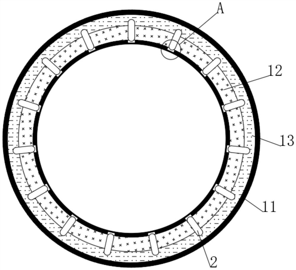
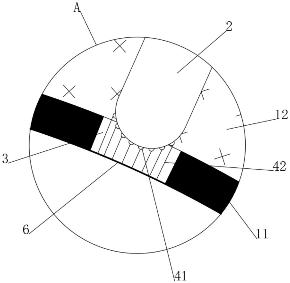
[0038] see figure 1 , a smoke exhaust pipe for a self-moving heat-removing type calciner, comprising a pipe body 11, an inner heat-conducting layer 12 is inlaid inside the pipe body 11, a heat-removing cavity 13 is dug inside the pipe body 11, and the outer end of the pipe body 11 is fixedly connected with a The water inlet pipe and the water outlet pipe, and the water inlet pipe and the water outlet pipe are all communicated with the heat removal chamber 13, and the condensed water circulation can be carried out in the heat removal chamber 13 through the water inlet pipe and the water outlet pipe. The heat removal chamber 13 is located outside the inner heat conducting layer 12, A plurality of uniformly distributed thermal reciprocating rods 2 are movably embedded in the inner heat conducting layer 12 .

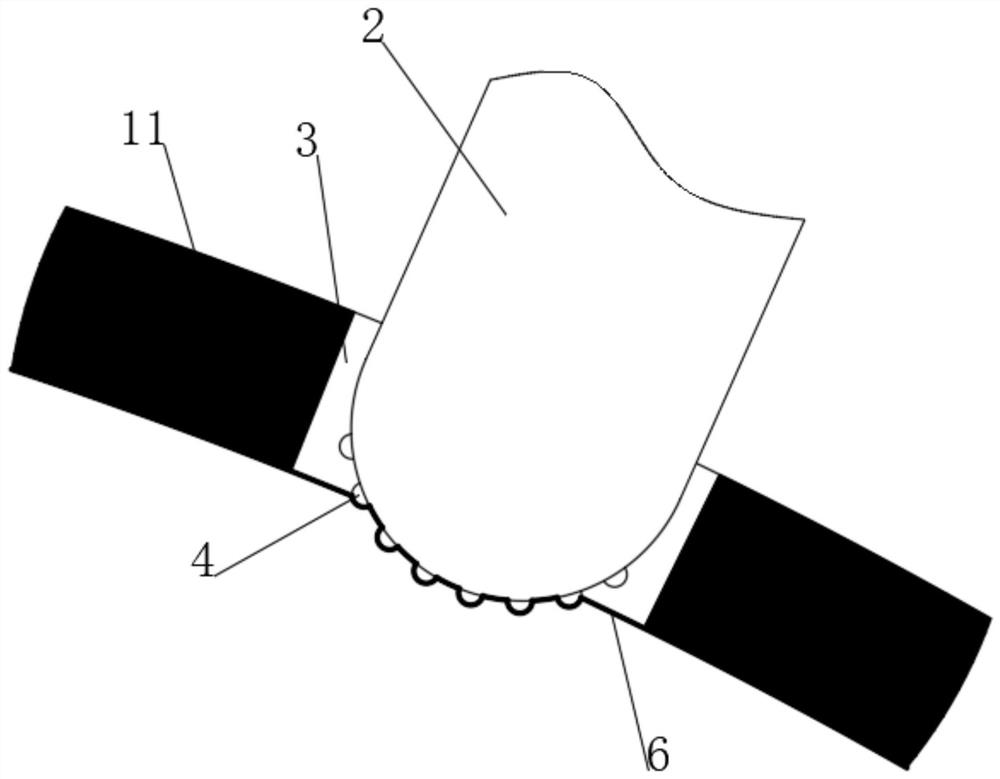
[0039] see figure 2 , the inner wall of 1 has a plurality of heat exchange holes 3 corresponding to the heat reciprocating rod 2, one end of the heat reciprocating rod 2 e...


PUM


Abstract

The invention discloses a self-moving heat removal type smoke exhaust pipeline for a calcining furnace, and belongs to the field of smoke exhaust. The self-moving heat removal type smoke exhaust pipeline for the calcining furnace comprises a pipeline body, wherein an inner heat conduction layer is embedded in the pipeline body; a heat removal cavity is dug in the pipeline body; and through the arrangement of a heat reciprocating rod and a bidirectional heat conduction rod on the heat reciprocating rod, when smoke is exhausted, a bidirectional heat bag performs bidirectional expansion deformation at the high temperature, and when the bidirectional heat conduction rod continuously moves back and forth in the inner heat conduction layer, on one hand, the bidirectional heat bag acts on an inner moving layer, the inner moving layer continuously and circularly protrudes to achieve the dynamic process of deformation recovery, and therefore the amount of smoke particles attached to the inner moving layer is effectively reduced, compared with the prior art, the cleaning difficulty and frequency of the pipeline are obviously reduced, and on the other hand, the exchange speed of heat carriedin the smoke and condensate water in the heat removal cavity can be effectively increased, the cooling efficiency of the smoke is higher, and potential safety hazards are obviously reduced.

Description

technical field [0001] The invention relates to the field of flue gas discharge, and more specifically relates to a flue gas exhaust pipe for a self-moving heat removal type calciner. Background technique [0002] Calciner is a kind of thermal equipment for heat treatment of carbon raw materials (such as coke, anthracite, etc.) at high temperature to improve the performance of raw materials. Equipment for iron making, recovery of rare metals, catalyst production, environmental improvement, and production of specialty chemicals. The characteristics of carbon raw materials determine the characteristics of calcination. [0003] Since the main component of carbon raw materials is carbon, which is flammable, direct contact with air should be avoided during the entire calcination process to reduce oxidation losses. It can be seen that indirect heating is suitable for calcination, and a reducing atmosphere should be established as much as possible during direct heating, and the a...

Claims


Application Information

Patent Timeline
IPC IPC(8): F27D17/00F28D21/00
CPCF27D17/002F28D21/00Y02P10/25
Inventor 刘思达
Owner 刘思达
Learn More