Eureka AIR delivers breakthrough ideas for toughest innovation challenges, trusted by R&D personnel around the world.

Continuous discharging mechanism for micro-diameter pipes

A pipe and micro-diameter technology, which is applied to other manufacturing equipment/tools, manufacturing tools, etc., can solve the problems of pipe bending deformation, cut-off end separation, and pipe cutting point cannot be completely pulled away, so as to achieve quantitative accuracy and avoid wear. Effect

Pending Publication Date: 2020-10-30
浙江康盛科工贸有限公司
View PDF1 Cites 0 Cited by
  • Summary
  • Abstract
  • Description
  • Claims
  • Application Information

AI Technical Summary

Problems solved by technology

There are still many problems in the existing technologies for cutting and blanking micro-diameter pipes. One is that the conveying pipes are basically carried out by special traction devices, and these traction devices are all pulled by clamping methods, so there are Second, due to the thin wall thickness of the micro-diameter tube, especially the soft texture of copper, aluminum and other tubes, after the circular cutting of the rotating cutter head, it is inevitable that there will be residual burrs after the circular cutting, so that the cutting point of the pipe cannot be completely pulled away, resulting in The cut-off end is not completely separated from the pipe end in progress, and the material cannot be dropped smoothly. This phenomenon will cause the pipe to bend, deform or even be scrapped. Otherwise, special guards are required to manually separate it.

Method used


Image

  • Continuous discharging mechanism for micro-diameter pipes
  • Continuous discharging mechanism for micro-diameter pipes
  • Continuous discharging mechanism for micro-diameter pipes

Examples


Embodiment Construction

[0027] The technical solutions of the present invention will be further specifically described below through the embodiments and in conjunction with the accompanying drawings.

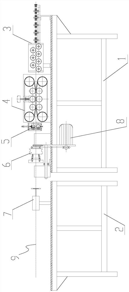
[0028] see figure 1 , the present embodiment is a continuous feeding mechanism for micro-diameter pipes, which consists of the main frame 1 and the blanking frame 2 arranged at the end of the main frame 1 along the central line 9 of the pipeline as the main body of the mechanism.

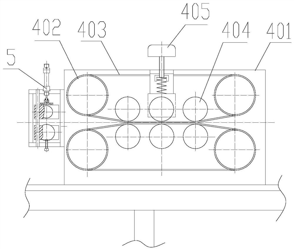
[0029] Wherein the main frame 1 has three parts: a straightening device 3, a belt conveyor 4 behind the straightening device 3, and a cutting device 6 behind the belt conveyor 3. Blanking frame 2 is mainly made up of clapping device 7 and blanking chute etc.

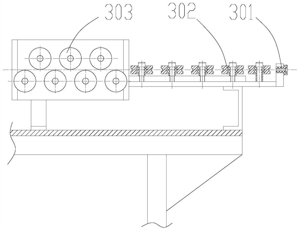
[0030] Straightening device 3 comprises one group of horizontal straightening wheels 302, and horizontal straightening wheels 302 is made up of 5 pairs of single wheels arranged horizontally, notch to notch; Horizontal straightening wheels 302 are followed by vertical...


PUM


Abstract

The invention discloses a continuous discharging mechanism for micro-diameter pipes. The mechanism comprises a main rack and a falling frame arranged at the tail end of the main rack along a conveyingpipe center line, and is characterized in that a straightening device is erected on the main rack, a belt conveying device is arranged behind the straightening device, and a cutting device is arranged behind the belt conveying device; and a clapping device is arranged on the falling frame and corresponds to the cutting device. In the whole discharging process, the micro-diameter pipes are pushedand conveyed through the friction force of a belt, so that the defects that the surfaces of the micro-diameter pipes are abraded and indentations are generated are avoided; and meanwhile, the micro-diameter pipes are further straightened, it is ensured that length determination of the micro-diameter pipes is more accurate, the problem that cutting points of pipe bodies cannot be completely pulledaway due to residual burrs caused by annular cutting is effectively solved, and the mechanism automatically works and is safe and reliable.

Description

technical field [0001] The invention relates to a micro-diameter pipe manufacturing technology, in particular to a micro-diameter pipe continuous feeding mechanism. Background technique [0002] The automatic and continuous feeding of pipes mainly considers the problems of pipe body transportation, fixed length and quantification, and material removal and separation. Currently, there are different feeding mechanism designs for pipes of different materials and purposes. For example, the patent publication number is CN107398730A, a pipe straightening and cutting machine, which is used for synchronous straightening and cutting of linear metal pipes. It has a multi-roller dislocation straightening mechanism, and the guiding device, straightening device, traction device, stroke counting encoder, cutting and pulling device, and clamping device are set on the workbench. In the cutting device, the cutting thrust block is used to push the cutting sliding sleeve, and the sliding The ...

Claims


Application Information

Patent Timeline
Patent Type & Authority Applications(China)
IPC IPC(8): B23P23/04
CPCB23P23/04
Inventor 王利春薛晓伟何柳滕世政周彬方林珍项崭
Owner 浙江康盛科工贸有限公司
Why Eureka
Eureka Blog
Learn More