Eureka AIR delivers breakthrough ideas for toughest innovation challenges, trusted by R&D personnel around the world.

Electrochemical fluorination external circulation electrolysis system

An electrolysis system and external circulation technology, which is applied in the field of electrochemical fluorination external circulation electrolysis system and electrolysis system, can solve the problems of cathode gas and anode gas explosion, low efficiency, and non-circulation of electrolyte, etc., to improve energy efficiency ratio and improve Recycling efficiency and effect of miniaturization

Active Publication Date: 2020-10-30
PERIC SPECIAL GASES CO LTD
View PDF7 Cites 3 Cited by
  • Summary
  • Abstract
  • Description
  • Claims
  • Application Information

AI Technical Summary

Problems solved by technology

The fluorinating agent in electrolytic production usually uses hydrogen fluoride, and the electrolyte and hydrogen fluoride are mixed in a certain proportion to form the electrolyte. The current fluorination electrolysis system uses the Simmons fluorination electrolysis system. The electrolyte does not circulate and is stored in square or round containers. The electrode is inserted into the electrolyte, and the heat generated by the electrode reaction is taken out of the system through the refrigerant installed in the coil pipe inside the electrolytic cell, resulting in a large volume and low efficiency of the fluorinated electrolytic cell. The upper part of the tank is a gas phase space, which is easy to cause the cathode gas and anode gas to mix and explode

Method used


Image

  • Electrochemical fluorination external circulation electrolysis system

Examples


Embodiment 1

[0025] Example 1: The system implements forced circulation

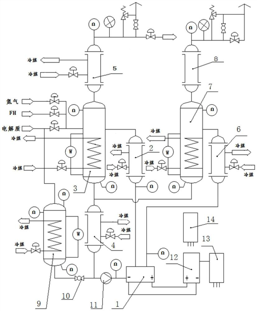
[0026]The control cabinet 14 is started, and the electrolyte and hydrogen fluoride enter the anode gas-liquid separator 3 through the control valve at a certain ratio, and continue to feed until the electrolyte level reaches the third point of the remote magnetic flap liquid level gauge in the anode gas-liquid separator 3 In one place, feeding is stopped, the circulation pump 11 is started after the nitrogen purge of the electrolysis system, and the rectifier cabinet 12 is started to transmit electricity. The anode gas and cathode gas respectively enter the anode cooler 2 and the cathode cooler 6 entrained with the electrolyte, and enter the anode gas-liquid separator 3 and the cathode gas-liquid separator 7 respectively after preliminary heat exchange. The gas phase in the anode gas and cathode gas rises into the anode condenser 5 and the cathode condenser 8, and after fully recovering the carried liquid components,...

Embodiment 2

[0027] Example 2: The system implements natural circulation

[0028] The control cabinet 14 is started, and the electrolyte and hydrogen fluoride enter the anode gas-liquid separator 3 through the control valve at a certain ratio, and continuously feed the electrolyte liquid level to the remote magnetic flap liquid level gauge in the anode gas-liquid separator 3. In one place, feed feeding is stopped, and after the electrolysis system is purged with nitrogen, the rectifier cabinet 12 starts power transmission, and under the action of the DC power supply, the cathode and anode reactions occur in the electrolysis cell 1 . The anode gas and cathode gas respectively enter the anode cooler 2 and the cathode cooler 6 entrained with the electrolyte, and enter the anode gas-liquid separator 3 and the cathode gas-liquid separator 7 respectively after preliminary heat exchange. The gas phase in the anode gas and cathode gas rises into the anode condenser 5 and the cathode condenser 8, a...

Embodiment 3

[0030] The cathode gas is directly discharged into the waste gas treatment tower without recovery, and the cathode cooler 6, cathode gas-liquid separator 7 and cathode condenser 8 can be removed from the entire electrolysis system. The control cabinet 14 is started, and the electrolyte and hydrogen fluoride enter the anode gas-liquid separator 3 through the control valve at a certain ratio, and continuously feed the electrolyte liquid level to the remote magnetic flap liquid level gauge in the anode gas-liquid separator 3. In one place, feeding is stopped, the circulation pump 11 is started after the nitrogen purge of the electrolysis system, and the rectifier cabinet 12 is started to transmit electricity. The anode gas engulfs the electrolyte and enters the anode cooler 2, and enters the anode gas-liquid separator 3 after preliminary heat exchange. The gas phase in the anode gas rises into the anode condenser 5, and after fully recovering the carried liquid components, it flo...


PUM


Abstract

The invention provides an electrochemical fluorination external circulation electrolysis system. The system comprises an electrolytic cell, an anode cooler, an anode gas-liquid separator, a main cooler, an anode condenser, a cathode cooler, a cathode gas-liquid separator and a cathode condenser. An anode liquid outlet of the electrolytic cell is connected with a liquid inlet of the anode cooler through a pipeline, and a liquid outlet of the anode cooler is connected with a liquid inlet in the upper portion of the anode gas-liquid separator through a pipeline. A liquid outlet in the bottom of the anode gas-liquid separator is connected with a liquid inlet in the top of the main cooler through a pipeline, and a liquid outlet in the bottom of the main cooler is connected with a liquid inlet of the electrolytic cell through a pipeline. The system facilitates miniaturization of the electrolytic cell, can eliminate the risks of refrigerant and electrolyte intermingling and negative and positive gas mixed explosion, obviously enhances the energy efficiency ratio of the electrolytic cell, is safe and reliable, finishes heat management by the coolers, can accurately control the electrolysistemperature, and can sufficiently obtain high-purity product gas through gas-liquid separation.

Description

technical field [0001] The invention belongs to the field of electrochemical fluorination and relates to an electrolysis system, in particular to an external circulation electrolysis system for electrochemical fluorination. Background technique [0002] The fluorination of compounds can be accomplished through synthetic chemical reactions or electrolysis. The conversion rate of chemical synthesis fluorination is low, the reaction is violent, the process is difficult to control, the safety risk is high, and there are many purification steps. Electrochemical fluorination is the use of electrode reactions to introduce fluorine atoms into organic or An effective way for inorganic substances, with high conversion rate and mild reaction. At present, the fluorination reactions of nitrogen trifluoride and perfluorosulfonyl fluoride are all completed by electrochemical fluorination process. [0003] The electrochemical fluorination system was invented by American chemist Simmons in ...

Claims


Application Information

Patent Timeline
Patent Type & Authority Applications(China)
IPC IPC(8): C25B9/00C25B3/08C25B15/08C25B15/02
CPCC25B9/00C25B15/08C25B15/02
Inventor 吝子东郝春辉冀延治李柄缘李林曹红梅杨雷雷袁瑞玲李虹璘
Owner PERIC SPECIAL GASES CO LTD
Why Eureka
Eureka Blog
Learn More