Compressed air jet type self-starting vertical axis wind turbine and detection method thereof

A wind turbine, self-starting technology, applied in the direction of the wind engine, wind engine, wind motor combination, etc. at right angles to the wind direction

Active Publication Date: 2020-10-30
SICHUAN UNIV
View PDF17 Cites 2 Cited by
  • Summary
  • Abstract
  • Description
  • Claims
  • Application Information

AI Technical Summary

Problems solved by technology

[0006] The purpose of the present invention is to provide a compressed air jet self-starting vertical axis wind turbine and its detection method, in order to improve the existing vertical axis wind turbine. If the auxiliary start of the motor is used, electric energy must be prepared in advance, and if the auxiliary start of the resistance blade is used, It is easy to cause the resistance type blade to become the resistance source when the lift type blade rotates at high speed

Method used


Image

  • Compressed air jet type self-starting vertical axis wind turbine and detection method thereof
  • Compressed air jet type self-starting vertical axis wind turbine and detection method thereof
  • Compressed air jet type self-starting vertical axis wind turbine and detection method thereof

Examples


Embodiment 1

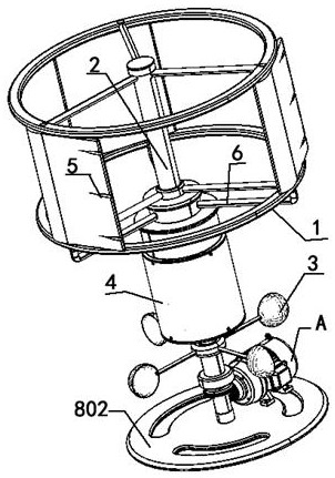
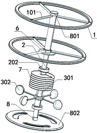
[0044] refer to Figure 1 to Figure 10 As shown, one embodiment of the present invention is a self-starting vertical axis wind turbine of a compressed air jet type, comprising a first impeller 1, and the above-mentioned first impeller 1 is installed on a power shaft 2, and is used for connecting the power shaft 2 and the power generating device The power connection, wherein the power generating device can be a generator A, the first impeller 1 is an existing lift-type impeller mechanism, the rotation of the first impeller 1 drives the power shaft 2 to rotate, and the power shaft 2 drives the generator A to work, and the power is generated by the power shaft 2. Machine A generates electricity.

[0045] A second impeller 3 is correspondingly provided on one side of the first impeller 1, that is, a second impeller 3 is arranged below or above the first impeller 1 to assist the rotation of the first impeller 1, wherein the second impeller 3 is an existing resistance type impeller ...

Embodiment 2

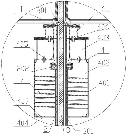
[0051] Based on the above embodiment and another embodiment of the present invention, the above-mentioned pressurized tank 4 includes a tank body 401, and the above-mentioned tank body 401 is provided with a pressurized chamber 402 and a high-pressure chamber 403, wherein the pressurized chamber 402 has the function of air pressurization , the high pressure chamber 403 plays the role of buffering the airflow. The lower end of the pressurizing chamber 402 is provided with an air inlet 404 with a downward opening, and the air inlet 404 of the pressurizing chamber 402 is placed downward and opens downward, thereby effectively preventing dust accumulation in the pressurizing chamber 402 .

[0052] It should be noted that, under the premise of ensuring that the air intake volume of the air inlet 404 meets the requirements, for the use environment of the wind turbine, the air inlet 404 can be installed with an anti-foreign matter cover 407 with air flow holes to prevent foreign matte...

Embodiment 3

[0058] Based on the above embodiments, refer to Figure 3 to Figure 5 As shown in another embodiment of the present invention, the above-mentioned power shaft 2 is hollow, the above-mentioned power shaft 2 is provided with a tower rod 8, the above-mentioned tower rod 8 is provided with a first bearing 801, and the movable end of the above-mentioned first bearing 801 is connected to the power shaft 2 The inner wall, that is, the tower rod 8 is a support rod, and the power shaft 2 is installed on the outside of the tower rod 8 through the first bearing 801 , so that the power shaft 2 can rotate when the tower rod 8 is stationary.

[0059] The lower end of the power shaft 2 is provided with a bevel gear 201 , which is used for power connection with the generator A by the bevel gear 201 . The bevel gear 201 is driven by the power shaft 2 to rotate, and the input shaft of the generator A is provided with an input gear that meshes with the bevel gear 201. The input gear rotates to d...


PUM


Abstract

The invention discloses a compressed air jet type self-starting vertical axis wind turbine and a detection method thereof. The compressed air jet type self-starting vertical axis wind turbine comprises a first impeller, wherein the first impeller is arranged on a power shaft and is used for being in power connection with a power generation device through the power shaft; a second impeller for driving the first impeller to rotate is correspondingly arranged on one side of the first impeller; a pressurizing tank is arranged between the second impeller and the first impeller; a shell of the pressurizing tank is arranged on the power shaft; an air jet hole is formed in the first impeller; an air conveying device is arranged on the pressurizing tank; the air conveying device communicates with the pressurizing tank and the air jet hole; air compression blades which rotate synchronously are arranged on the second impeller; and the air compression blades are arranged in an inner cavity of thepressurizing tank. According to the compressed air jet type self-starting vertical axis wind turbine and the detection method thereof, the problem that an existing vertical axis lift type wind turbinecannot be self-started or when resistance type blades are adopted to assist the lift type blades to start, the resistance type blades are prone to becoming a resistance source when the lift type blades rotate at a high speed is expected to be solved.

Description

technical field [0001] The invention relates to new energy wind power generation equipment, in particular to a compressed air jet type self-starting vertical axis wind turbine and a detection method thereof. Background technique [0002] With the progress of the times, the rational use of natural resources has received extensive attention, and wind turbines have been gradually put into the market to reduce the consumption of fossil energy and environmental pollution. Among them, the vertical axis wind turbine can utilize the wind energy blown from all directions because it does not need a steering mechanism, which has unique advantages compared with the horizontal axis wind turbine. [0003] Existing vertical-axis wind turbines generally use lift-type or drag-type blades. Lift-type vertical-axis wind turbines have higher wind energy utilization rates, but lift-type vertical-axis wind turbines cannot be self-started. They need to be equipped with motors to assist in starting,...

Claims


Application Information

Patent Timeline
Patent Type & Authority Applications(China)
IPC IPC(8): F03D3/00F03D3/06F03D7/06F03D17/00F03D13/20F03D9/25
CPCF03D3/005F03D3/062F03D7/06F03D9/25F03D13/20F03D17/00Y02E10/728Y02E10/74
Inventor 冯成德邢林春
Owner SICHUAN UNIV
Why Eureka
Try Eureka