Blast furnace lining thickness calculation device and method based on distributed optical fiber temperature measurement

A technology of distributed optical fiber and calculation method, which is applied in thermometers, measuring devices, thermometers with physical/chemical changes, etc. problem, to achieve the effect of rapid positioning and reducing the risk of safety production

Pending Publication Date: 2020-10-30
CISDI ENG CO LTD +1
View PDF0 Cites 3 Cited by
  • Summary
  • Abstract
  • Description
  • Claims
  • Application Information

AI Technical Summary

Problems solved by technology

However, due to the safety limit of the number of openings in the furnace shell, the thermocouples in the circumferential direction are generally spaced 1m to 3m apart. Therefore, the number of temperature monitoring is limited, which is not enough to implement full-coverage detection of the hearth circumference, and the obtained hearth lining residual Thickness monitoring has a large monitoring blind spot, which makes it impossible to monitor the thickness of the blast furnace lining in all directions and with full coverage, which brings great safety hazards to blast furnace production

Method used


Image

  • Blast furnace lining thickness calculation device and method based on distributed optical fiber temperature measurement
  • Blast furnace lining thickness calculation device and method based on distributed optical fiber temperature measurement
  • Blast furnace lining thickness calculation device and method based on distributed optical fiber temperature measurement

Examples


specific Embodiment

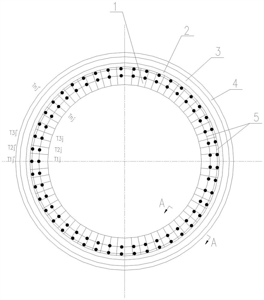
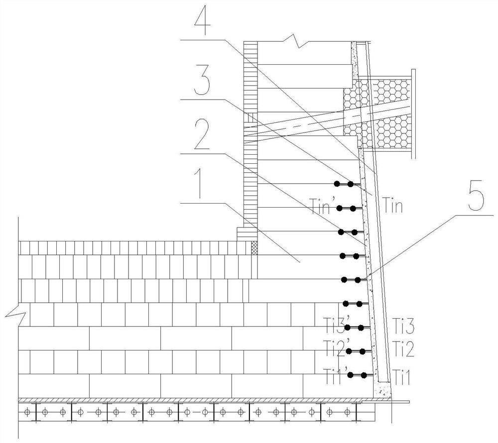
[0087] Specific embodiment: Taking a blast furnace hearth as an example, two rings of distributed optical fibers 2 are arranged in the inner ring lining 1 of each layer of the blast furnace hearth. Since the distributed optical fibers can set multiple points along the optical fiber path, for the convenience of display, each layer Only 25 optical fiber temperature measuring points are set in the inner ring lining 1 circumferential direction.

[0088] 2 layers of temperature measuring optical fibers in the circumferential direction 2 spacing L 0 =100mm, the distance L between the inner ring fiber and the cold surface of the inner lining 1 =200mm.

[0089] The thermal conductivity of the refractory lining 1 is λ=18w / m.℃;

[0090] The melting temperature of the iron layer is 1150°C;

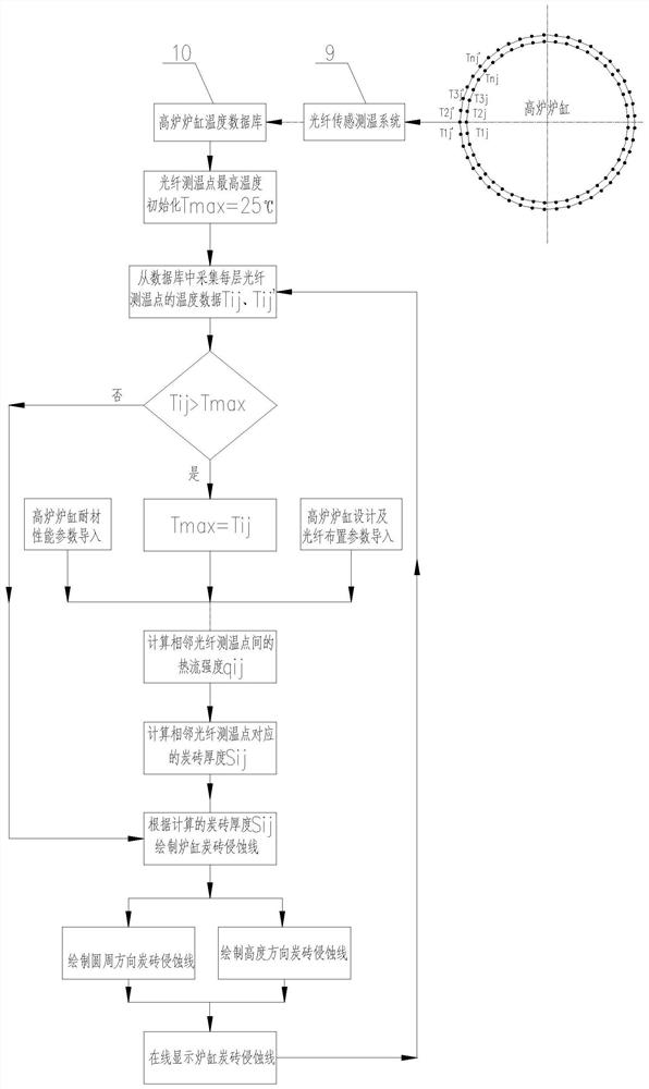
[0091] Initialize the maximum temperature T of the blast furnace hearth refractory lining max =25°C

[0092] When the temperature measurement data T of the 2-ring distributed optical fiber 2 in ...


PUM

PropertyMeasurementUnit
thermal conductivityaaaaaaaaaa

Abstract

The invention relates to a blast furnace lining thickness calculation device and method based on distributed optical fiber temperature measurement, and belongs to the technical field of blast furnaces. The device comprises a refractory lining, a joint mixture, cooling equipment, a blast furnace shell, distributed optical fibers, an optical fiber sensing and temperature measuring system and a blastfurnace hearth temperature database. Based on the optical fiber temperature measurement principle, the optical fibers are laid in the industrial furnace lining in the circumferential direction and the height direction of the furnace lining respectively, the temperatures of the corresponding positions of corresponding scattering areas can be obtained through Rayleigh scattering light, Raman scattering light and Brillouin scattering light obtained in all the scattering areas in the optical fibers, and the minimum distance between every two adjacent temperature measurement points can reach the millimeter level; meanwhile, a heat transfer theory is utilized to calcualte the heat flow intensity and the residual thickness of the blast furnace hearth lining, so that the traditional thermocoupletemperature monitoring mode can be replaced, the abnormal erosion point of the lining can be positioned for 24 hours according to the temperature and the residual thickness of the blast furnace hearthlining, the safety production risk of the blast furnace is reduced, and a guarantee is provided for efficient and safe production of the blast furnace.

Description

technical field [0001] The invention belongs to the technical field of blast furnaces, and relates to a blast furnace lining thickness calculation device and method based on distributed optical fiber temperature measurement. Background technique [0002] As the main method of modern ironmaking, the blast furnace accounts for more than 90% of the world's total ironmaking output. It is currently the most efficient, low-consumption, and environmentally friendly leading ironmaking equipment. However, in recent years, blast furnaces at home and abroad have frequently experienced burn-through accidents of their inner linings, and suffered from abnormal erosion of the hearth lining carbon bricks. The reduction seriously threatens the safe production of the blast furnace and causes huge economic losses to the enterprise. Therefore, real-time monitoring of the thickness of the blast furnace lining to prevent the blast furnace from being burned through is of great significance to the...

Claims


Application Information

Patent Timeline
Patent Type & Authority Applications(China)
IPC IPC(8): G01B21/08G01K11/32
CPCG01B21/085G01K11/32
Inventor 赵运建牛群邹忠平许俊钟星立王刚
Owner CISDI ENG CO LTD
Why Eureka
Try Eureka