
Broadband collinear slot waveguide slot antenna

A waveguide slot antenna, collinear technology, applied in the direction of leaky waveguide antenna, antenna grounding switch structure connection, radiating element structure form and other directions, can solve the problems of affecting amplitude and phase distribution, waveguide wavelength change, complex processing, etc., to improve polarization Isolation, cross-polarization level improvement, and parasitic sidelobe suppression effect

Active Publication Date: 2020-10-30
CHINA ELECTRONICS TECH GRP CORP NO 14 RES INST
View PDF15 Cites 5 Cited by
  • Summary
  • Abstract
  • Description
  • Claims
  • Application Information

AI Technical Summary

Problems solved by technology

This patent uses an asymmetrical ridge waveguide to realize collinear slots. Compared with dislocation line slots, the cross-polarization performance is improved and parasitic sidelobes are not easy to occur, but there are the following problems: First, the structure is complex, resulting in complex processing and high processing costs. , which is not conducive to large-scale application; secondly, due to the discontinuous section of the waveguide cavity, the wavelength of the waveguide changes significantly, which seriously affects the amplitude and phase distribution of each slot and reduces the radiation efficiency of the waveguide slot antenna; thirdly, the volume is large

Method used


Image

  • Broadband collinear slot waveguide slot antenna
  • Broadband collinear slot waveguide slot antenna
  • Broadband collinear slot waveguide slot antenna

Examples


Embodiment 1

[0035] An embodiment of the present invention is a broadband collinear slot waveguide slot antenna.

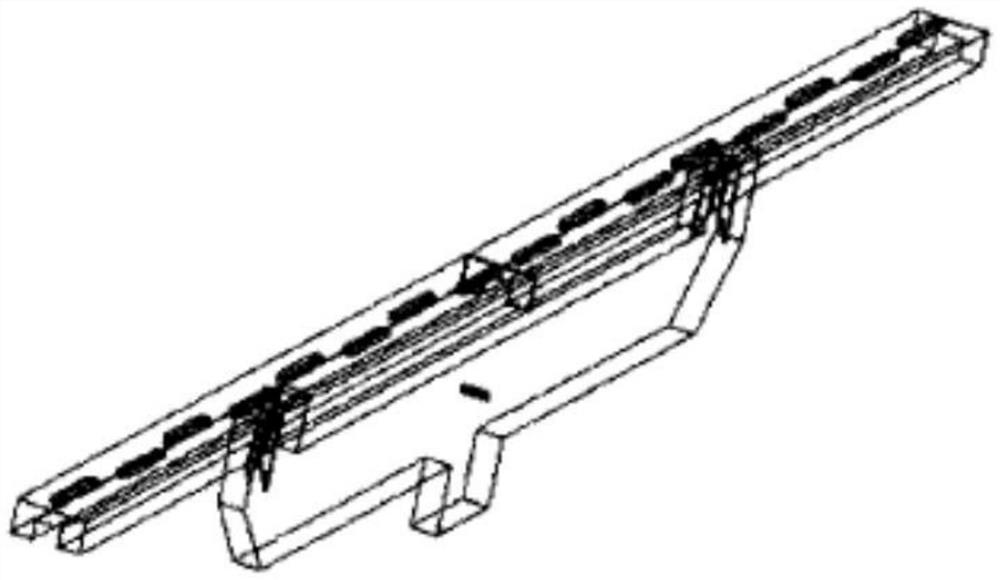
[0036] like Figure 2 to Figure 7 As shown, the broadband collinear slot waveguide slot antenna of this embodiment includes: a waveguide-to-coaxial converter 1 , a one-to-two feed waveguide 2 and a radiation waveguide 5 . The one-to-two feed waveguide 2 and the radiation waveguide 5 adopt a symmetrical nesting design, and the two are separated by a common wall 23 .

[0037] like Figure 5 ~ Figure 7 As shown, the feed waveguide 2 divided into two includes a bottom plate 21, a feed waveguide separation wall 22, and a common wall 23 to form a feed waveguide cavity. The waveguide coaxial converter 1 is located at the center of the lower side of the one-to-two feed waveguide 2 and integrated with the one-to-two feed waveguide 2 . The two-point feeding waveguide 2 is combined with the radiation waveguide 5 up and down, and is separated into a lower feeding waveguide cavity and a...


PUM


Abstract

The invention discloses a broadband collinear slot waveguide slot antenna, and belongs to the technical field of microwave antennas. The antenna comprises a waveguide coaxial converter, a one-to-two feed waveguide and a radiation waveguide. The one-to-two feed waveguide and the radiation waveguide are symmetrically nested and combined and are separated by a common common wall; the waveguide coaxial converter is located in the center of the lower side of the one-to-two feed waveguide, and isolation walls are arranged at the two ends of the one-to-two feed waveguide and the radiation waveguide and the joint of the radiation waveguide and the waveguide coaxial converter and used for forming a closed waveguide cavity. A plurality of radiation slots are formed in the top of the radiation waveguide along the center line of the wide edge direction, the radiation slots are located on the same straight line, and disturbance blocks which are distributed alternately are arranged in a waveguide cavity of the wave radiation waveguide near the radiation slots. The broadband collinear slot waveguide slot antenna provided by the invention is wide in working bandwidth, good in cross polarization performance and not easy to generate parasitic side lobes.

Description

technical field [0001] The invention belongs to the technical field of microwave antennas, and in particular relates to a broadband collinear slot waveguide slot antenna. Background technique [0002] At present, the radar system is developing towards high resolution, multi-polarization and multi-mode as the demand guides. As one of the key subsystems of the radar system, the antenna needs to have functions such as broadband and low cross-polarization. The waveguide slot antenna has the characteristics of high efficiency, small size, light weight, compact structure, easy to obtain high gain, and has been widely used in radar and microwave communication systems. Since the birth of the waveguide slot antenna, people have carried out a lot of related research, and achieved fruitful results in theoretical research and engineering applications. [0003] At present, the waveguide slot antenna mainly has two types of slots: wide-side slot and narrow-side slot. The staggered distri...

Claims


Application Information

Patent Timeline
Patent Type & Authority Applications(China)
IPC IPC(8): H01Q1/50H01Q1/36H01Q13/22
CPCH01Q1/36H01Q1/50H01Q13/22
Inventor 宋国栋宋洪飞梁志伟张金平李锐倪华昌
Owner CHINA ELECTRONICS TECH GRP CORP NO 14 RES INST
Learn More