Ditch dredging equipment applied to hydraulic engineering

A technology for water conservancy projects and ditches, which is applied in the fields of environmental protection and silt removal, and can solve problems such as low efficiency, unsafe personal safety, and poor water flow.

Inactive Publication Date: 2020-11-03
安徽绪稻康建筑工程咨询有限公司
View PDF0 Cites 8 Cited by
  • Summary
  • Abstract
  • Description
  • Claims
  • Application Information

AI Technical Summary

Problems solved by technology

[0002] Drainage ditch refers to the ditch that guides the water collected in the side ditch of road construction, intercepting ditch, and low-lying places near the roadbed, in the crop field, and near the residence to the ditch outside the roadbed, crop field, and residential area. The design of the drainage ditch is based on the drainage system engineering layout and engineering. Standards, determine the depth and spacing of field drainage ditches, and analyze and calculate the flow, water level, section size and engineering volume of drainage ditches and buildings at all levels, but the sediment accumulation in the existing road construction maintenance drainage ditch is too much The blockage will cause poor water flow or water overflow to the road building, and the existing drainage ditch dredging device for road building maintenance uses manual salvage and removal of floating garbage, which has low efficiency and no guarantee for personal safety. Therefore, in Carrying out further research on the basis of existing drains, it is imperative to provide a drain dredging device for road construction maintenance. The silt at the bottom of the ditch is automatically cleared, and the frame width of the automatic traveling device can be adjusted according to the actual width of the ditch, and the height of the self-adaptive dredging device can be adjusted according to the actual height of the ditch. The opening angles of the two sets of guide plates that guide the accumulation of silt can be adjusted according to the actual width of the ditch, so that the dredger can adapt to ditch with different widths and heights, and the scope of application is wider. Better dredging effect

Method used


Image

  • Ditch dredging equipment applied to hydraulic engineering
  • Ditch dredging equipment applied to hydraulic engineering
  • Ditch dredging equipment applied to hydraulic engineering

Examples


Embodiment Construction

[0076] The specific implementation manners of the present invention will be further described below in conjunction with the drawings and examples. The following examples are only used to illustrate the technical solution of the present invention more clearly, but not to limit the protection scope of the present invention.

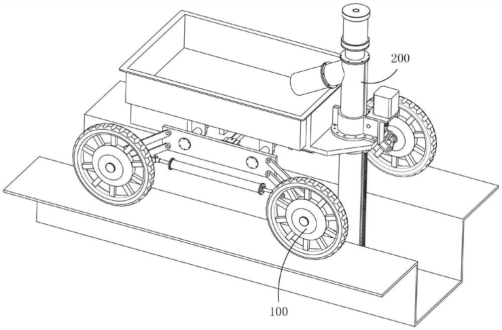
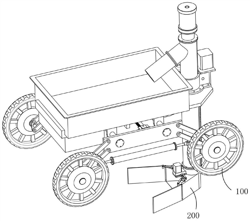
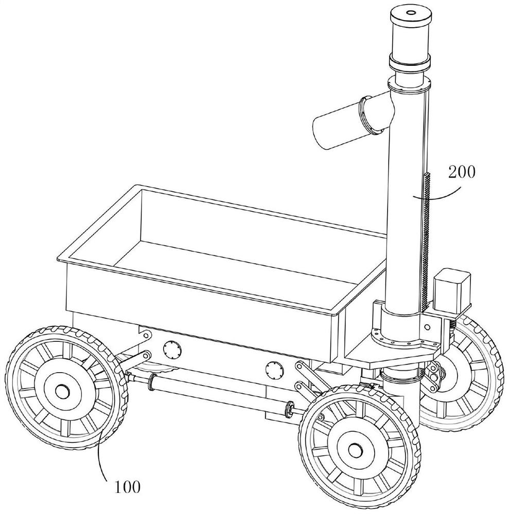
[0077] Ditch dredging equipment applied to water conservancy projects, which includes an automatic traveling device 100, an adaptive dredging device 200 installed on the automatic traveling device 100, the automatic traveling device 100 is used to pull the dredging machine forward along the direction of ditch extension and The vehicle width of the automatic traveling device 100 can be adjusted according to the actual width of the ditch, and the self-adaptive dredging device 200 is used to remove the silt in the ditch while following the automatic traveling device 100 and the self-adaptive dredging device 200 The width can be adaptively adjusted according to...


PUM


Abstract

The invention provides ditch dredging equipment applied to hydraulic engineering. The ditch dredging equipment comprises an automatic advancing device and a self-adaptive dredging device installed onthe automatic advancing device, the automatic advancing device is used for dragging the dredging equipment to advance in the ditch extending direction, and the width of the automatic advancing devicecan be adjusted according to the actual width of a ditch; the self-adaptive dredging device is used for removing silt in the ditch in the process of advancing along with the automatic advancing device, and the width of the self-adaptive dredging device can be adjusted according to the actual width of the bottom of the ditch; the slit at the bottom of the ditch can be automatically removed, the width of a frame of the automatic advancing device can be adjusted according to the actual width of the ditch, and the height of the self-adaptive dredging device can be adjusted according to the actualheight of the ditch; and the opening angles of two sets of guide plates, playing a role in guiding and gathering the slit, of the self-adaptive dredging device can be adjusted according to the actualwidth of the ditch. The ditch dredging equipment can adapt to different ditches, and the dredging effect on the slit in the ditches is better.

Description

technical field [0001] The invention relates to the field of environmental protection, in particular to the field of sludge removal. Background technique [0002] Drainage ditch refers to the ditch that guides the water collected in the side ditch of road construction, intercepting ditch, and low-lying places near the roadbed, in the crop field, and near the residence to the ditch outside the roadbed, crop field, and residential area. The design of the drainage ditch is based on the drainage system engineering layout and engineering. Standards, determine the depth and spacing of field drainage ditches, and analyze and calculate the flow, water level, section size and engineering volume of drainage ditches and buildings at all levels, but the sediment accumulation in the existing road construction maintenance drainage ditch is too much The blockage will cause poor water flow or water overflow to the road building, and the existing drainage ditch dredging device for road build...

Claims


Application Information

Patent Timeline
Patent Type & Authority Applications(China)
IPC IPC(8): E02F5/28
CPCE02F5/28
Inventor 不公告发明人
Owner 安徽绪稻康建筑工程咨询有限公司
Why Eureka
Try Eureka