Water level monitoring and alarming device for hydraulic engineering and implementation method thereof
A water level monitoring and alarm device technology, applied in the direction of measuring devices, heating devices, circuit devices, etc., can solve the problems of general alarms, inability to subdivide alarms, high cost, etc., to prevent data loss, reduce property losses, and fast timeliness Effect
- Summary
- Abstract
- Description
- Claims
- Application Information
AI Technical Summary
Problems solved by technology
Method used
Image
Examples
Embodiment 1
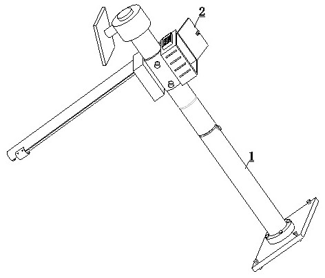
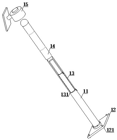
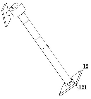
[0038] refer to figure 1 , 2 , 6 and 8, a water level monitoring and alarm device for water conservancy projects, including a support mechanism 1 and a monitoring mechanism 2, one end of the support mechanism 1 is provided with a monitoring mechanism 2, and the support mechanism 1 includes a main support rod 11, a pre-fixed plate 12 , a splicing rod 13, a strengthening telescopic tube 14 and an energy supply mechanism 15, one end of the main strut 11 is fixedly equipped with a pre-fixed plate 12, the other end of the main strut 11 is provided with a splicing rod 13, and the outer surface of the splicing rod 13 is covered Connected with reinforced telescopic cylinder 14, one end of reinforced telescopic cylinder 14 is provided with energy supply mechanism 15, and the outer surface of strengthened telescopic cylinder 14 is provided with monitoring mechanism 2, and monitoring mechanism 2 comprises main body mechanism 21 and sliding mechanism 22, and main body mechanism 21 One si...
Embodiment 2
[0040] refer to Figure 4 and 9 , the main strut 11 includes a first-level lifting rod 111, a second-level lifting rod 112, a third-level lifting rod 113 and a locking bolt 114. The inside of the first-level lifting rod 111 is provided with a second-level lifting rod 112, and the second-level lifting rod 112 The interior is provided with a three-level lifting rod 113, the outer surfaces of the first-level lifting rod 111 and the second-level lifting rod 112 are provided with locking bolts 114, and the second-level lifting rod 112 is movably connected with the first-level lifting rod 111 through the locking bolt 114 , the third-level lifting rod 113 is flexibly connected with the second-level lifting rod 112 through the locking bolt 114, one end of the first-level lifting rod 111 is connected with the splicing rod 13, and the energy supply mechanism 15 includes a spin base 151, a fixed rod 152 and a solar cell plate 153, one end of the fixed rod 152 is provided with a spin bas...
Embodiment 3
[0042] refer to Figure 6 and 7 , the main mechanism 21 includes a collar tube 211, a control box 212 and a storage box 213, a control box 212 is fixedly installed on one side of the collar tube 211, a storage box 213 is fixedly installed on the other side of the collar tube 211, and a storage box 213 is fixedly installed on the collar tube 211. 211 is provided with a fixed pin 2111 on the outer surface, and the collar tube 211 is movably connected with the reinforced telescopic tube 14 through the fixed pin 2111. The inside of the control box 212 is provided with an alarm 2121, a storage battery 2122, an information collection module 2123 and an information transmission module 2124 , the storage battery 2122 is electrically connected to the solar panel 153, the information collection module 2123 and the information sending module 2124 are both connected to the alarm 2121, the inside of the storage box 213 is provided with a partition 2131, and the outer surface of the partiti...
PUM
 Abstract
Description
Claims
Application Information
 - R&D
- Intellectual Property
- Life Sciences
- Materials
- Tech Scout
- Unparalleled Data Quality
- Higher Quality Content
- 60% Fewer Hallucinations
Browse by: Latest US Patents, China's latest patents, Technical Efficacy Thesaurus, Application Domain, Technology Topic, Popular Technical Reports.
© 2025 PatSnap. All rights reserved.Legal|Privacy policy|Modern Slavery Act Transparency Statement|Sitemap|About US| Contact US: help@patsnap.com


