A Control Method of Pumping Unit Based on Motor Power Torque

A technology of motor power and control method, applied in the direction of AC motor control, control system, software algorithm control, etc., can solve problems such as failure of a single pumping unit, poor quality of the feedback unit feedback grid waveform, and great influence on the grid, so as to reduce The effect of labor intensity and spare parts, reducing wear and tear of ineffective equipment, and reducing motor energy consumption

Active Publication Date: 2022-02-01
PETROCHINA CO LTD
View PDF0 Cites 0 Cited by
  • Summary
  • Abstract
  • Description
  • Claims
  • Application Information

AI Technical Summary

Problems solved by technology

[0007] Adding braking resistors to release the energy consumption of the overvoltage during the down process of the pumping unit, also known as resistor energy consumption braking, this method is simple and the installation cost is low, but it is a serious waste of electric energy
[0008] The parallel control of the common DC bus of multiple units transmits the energy in the downlink process to other frequency converters in the uplink process. This method is simple for cluster wells and has a good energy-saving effect, but it is not good for a single pumping unit.
[0009] Install an energy feedback unit or use a four-quadrant special frequency converter to feed back the energy in the downlink process to the grid. This method is costly, and the waveform quality of some feedback units fed back to the grid is very poor, which has a great impact on the grid and is not suitable for large-scale Area promotion application

Method used


Image

  • A Control Method of Pumping Unit Based on Motor Power Torque
  • A Control Method of Pumping Unit Based on Motor Power Torque
  • A Control Method of Pumping Unit Based on Motor Power Torque

Examples


Embodiment 1

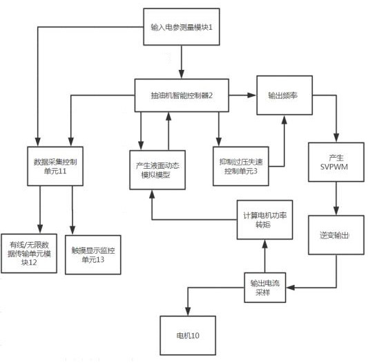
[0035] Such as figure 1 As shown, a pumping unit control method based on motor power torque includes the following steps:

[0036] The first step is to establish a liquid level dynamic simulation model.

[0037] In the second step, the intelligent controller of the pumping unit controls the operation of the motor;

[0038] In the third step, the pumping speed of the pumping unit is changed to obtain the motor power torque of the motor 10, and the intelligent controller 2 of the pumping unit adjusts the operating frequency of the motor 10 according to the relevant parameters of the dynamic simulation model of the liquid level and the power torque of the motor. Thereby changing the pumping speed of the pumping machine;

[0039] The fourth step is to stop working in intermittent pumping mode.

[0040] When the power torque of the motor conforms to the empty pumping state in the liquid level dynamic simulation model, the intelligent controller 2 of the pumping unit controls the...

Embodiment 2

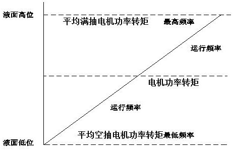
[0050] On the basis of Example 1, such as figure 1 As shown, the method for establishing the liquid level dynamic simulation model is that the intelligent controller 2 of the pumping unit self-learns the average full pumping motor power torque, the average empty pumping motor power torque and the theoretical interval time between pumping pumps, and according to the self-learning average full pumping The power torque of the pumping motor and the average power torque of the empty pumping motor are used to establish a dynamic simulation model of the liquid level.

[0051] Let the intelligent controller 2 of the pumping unit perform self-study first to obtain the average full pumping motor power torque, average full pumping motor power torque and theoretical pumping interval time, and establish a liquid level dynamic simulation model to prepare for subsequent comparisons .

[0052] The self-learning method of pumping unit intelligent controller 2 is as follows: 1) Full pumping to...

Embodiment 3

[0061] On the basis of Example 2, such as figure 1 As shown, in the second step, the method for the intelligent controller 2 of the pumping unit to control the operation of the motor 10 is that the intelligent controller 2 of the pumping unit gives the motor 10 a current with an initial output frequency, and the current is delivered to the motor 10 and then dragged. The motor 10 operates. The pumping unit can only provide a current to the motor 10 by the controller 2, and the operating frequency of the motor 10 is also different according to the output frequency of the current.

[0062] The specific current at the initial output frequency is modulated to generate SVPWM, and the SVPWM is output by inverter and then sent to the motor 10 to drive the motor 10 to work.

[0063] The output frequency of the output current of the pumping unit intelligent controller 2 is adjusted every 5 minutes. The output current is sampled every 5 minutes, and the result is fed back to the intell...


PUM


Abstract

The invention discloses a control method for a pumping unit based on the power torque of a motor, which comprises the following steps. In the second step, the intelligent controller of the pumping unit gives the motor an output frequency, the output frequency is modulated to generate SVPWM, and the SVPWM drives the motor to operate after outputting through the inverter; the third step is to input electric parameters to measure The module samples the output current of the inverter output to obtain the output current change signal, and calculates the motor power torque from the output current change signal, and the intelligent controller of the pumping unit adjusts the output frequency, thereby adjusting the motor operating frequency and changing the pumping speed . Through the real-time change of the current / torque of the motor, the output speed required in real time can be obtained to achieve better energy-saving effects, achieve a balance between supply and production, improve the efficiency of mechanical production, and reduce the energy consumption of pumping units during oil production.

Description

technical field [0001] The invention belongs to the technical field of oil production control, and in particular relates to a method for controlling an oil pumping unit based on the power torque of a motor. Background technique [0002] The pumping unit is the most important power-consuming equipment in the process of oilfield exploitation, and the beam pumping unit is generally used now. When the pumping unit is started, the current is relatively large. In order to start reliably, the motors of the pumping unit are generally selected and enlarged. This will cause the situation of large horses and small carts in the normal operation of the motor, and the operating efficiency is low. At the same time, there are often many old oil wells in oil fields that have been in operation for many years, and the oil production of oil wells is not very fixed. The plunger pump often works in empty pumping or insufficient oil pumping, which leads to ineffective wear of the mechanical equip...

Claims


Application Information

Patent Timeline
Patent Type & Authority Patents(China)
IPC IPC(8): H02P23/00E21B43/12
CPCH02P23/0077E21B43/127
Inventor 刘一山刘汉斌薛建强王林平魏立军费二战晏耿成石磊
Owner PETROCHINA CO LTD
Why Eureka
Try Eureka