Hydraulic ball valve shell corrosion prevention treatment device

A technology of anti-corrosion treatment and casing, which is applied to the surface coating liquid device, workpiece clamping device, coating, etc., can solve the problems of long time consumption, low work efficiency, high production cost, etc., to avoid relative sliding, work Low efficiency, avoiding the effect of falling

Active Publication Date: 2020-11-06
JIANGXI HYDRAULIC PIECES
View PDF6 Cites 3 Cited by
  • Summary
  • Abstract
  • Description
  • Claims
  • Application Information

AI Technical Summary

Problems solved by technology

[0005] The present invention provides a hydraulic ball valve shell anticorrosion treatment device, which can solve the following problems in the process of painting the shell: a. This type of fixture can only correspond to one type of shell. When grinding the shells of different specifications, different fixtures need to be replaced. The process is more cumbersome and the production cost is higher. Apply anti-corrosion treatment to the surface of one side of the shell. When it is necessary to paint both sides of the shell, it is necessary to change the direction of the shell many times, which is time-consuming and low in work efficiency. The length is fixed, and the length of the brushing execution section cannot be adjusted according to the length of the shell, which may lead to poor brushing effect and affect the use

Method used


Image

  • Hydraulic ball valve shell corrosion prevention treatment device
  • Hydraulic ball valve shell corrosion prevention treatment device
  • Hydraulic ball valve shell corrosion prevention treatment device

Examples


Embodiment Construction

[0030] The embodiments of the present invention will be described in detail below with reference to the accompanying drawings, but the present invention can be implemented in many different ways defined and covered by the claims.

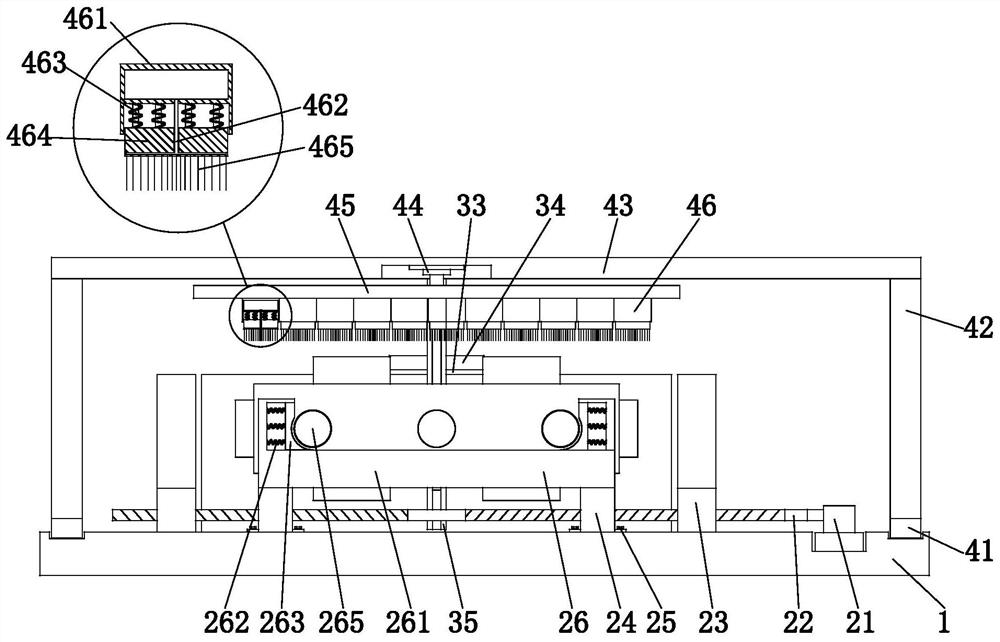
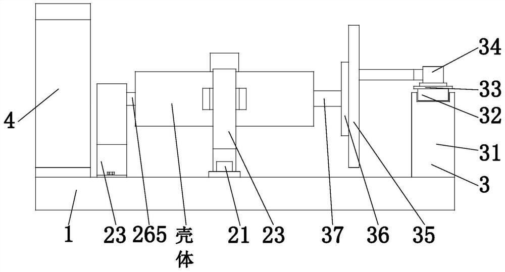
[0031] Such as Figure 1 to Figure 7 As shown, a hydraulic ball valve shell anticorrosion treatment device includes a bottom frame 1, a clamping and placing mechanism 2, a turning mechanism 3, and a brushing mechanism 4. The upper end surface of the bottom frame 1 is sequentially installed with turning Mechanism 3 , clamping and placing mechanism 2 and brushing mechanism 4 , wherein the brushing mechanism 4 is slidably arranged on the bottom frame 1 .

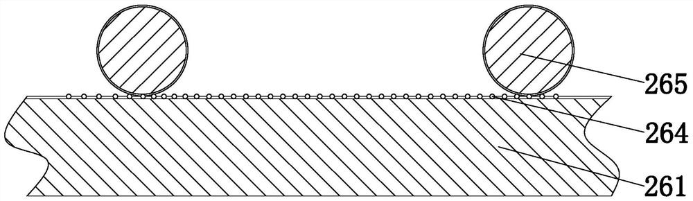
[0032] The clamping and placing mechanism 2 includes a rotating motor 21, a lead screw 22, a clamping column 23, a support block 24, a fixing bolt 25 and a placing branch chain 26, wherein the upper end surface of the bottom frame 1 has a No. 1 groove , the rotating motor 21 is installed in the No. ...


PUM


Abstract

The invention relates to a hydraulic ball valve shell corrosion prevention treatment device comprising a bottom machine frame, a clamping and containing mechanism, a turnover mechanism and a brushingmechanism. The hydraulic ball valve shell corrosion prevention treatment device can solve the following problems of a hydraulic ball valve shell in the brushing process, wherein the problems include the problem a that in the process of conducting corrosion prevention treatment through traditional brushing, due to the fact that when the shell is clamped, one clamp can only correspond to one specification of shells, replacement of different clamps needs to be conducted correspondingly when polishing work is conducted on different specifications of shells, the process flow is tedious and the production cost is high, the problem b that due to the fact that in existing devices, generally surface brushing corrosion prevention treatment can only be conducted on a single side of the shell, when two sides of the shell need to be brushed, the direction of the shell needs to be changed multiple times, the consumed time is long and the work efficiency is low and the problem c that due to the factthat the length of the brushing execution end of an existing brushing device is fixed and the length of the brushing execution section cannot be regulated according to the length of the shell, the brushing effect can be poor and use is influenced.

Description

technical field [0001] The invention relates to the field of hydraulic ball valve processing, in particular to an anticorrosion treatment device for a hydraulic ball valve shell. Background technique [0002] The hydraulic ball valve is a valve that uses the valve stem to drive the ball and rotates around the axis of the valve stem. Its external shape is as follows: Figure 7 As shown, the hydraulic ball valve is widely used in petroleum refining, long-distance pipeline, chemical industry, steel and other industries due to its compact structure, reliable sealing, simple structure, and suitable for harsh working conditions. There are many bodies, and the method of casting is often used. In actual production and life, the surface of the shell after casting needs to be further refined such as grinding and anti-corrosion treatment. [0003] At present, the following problems exist in the painting process of hydraulic ball valve housings: a. During the anticorrosion treatment pro...

Claims


Application Information

Patent Timeline
Patent Type & Authority Applications(China)
IPC IPC(8): B25B11/00B05C13/02
CPCB25B11/00B05C13/02
Inventor 杨华陈益标朱丹青
Owner JIANGXI HYDRAULIC PIECES
Why Eureka
Try Eureka