Dry type mechanical vacuum system and vacuum pumping method for molten steel high-vacuum refining furnace
A vacuum system and mechanical vacuum pump technology, applied in the field of high vacuum for iron and steel metallurgy, can solve the problems of being easily affected by external factors, burning cloth bags of dust collectors, and rising operating temperature of vacuum pumps, so as to eliminate the phenomenon of burning cloth bags, ensure low failure rate, The effect of improving the operating life
- Summary
- Abstract
- Description
- Claims
- Application Information
AI Technical Summary
Problems solved by technology
Method used
Image

Examples
Embodiment Construction
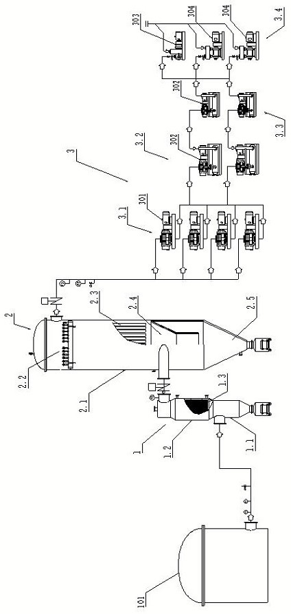
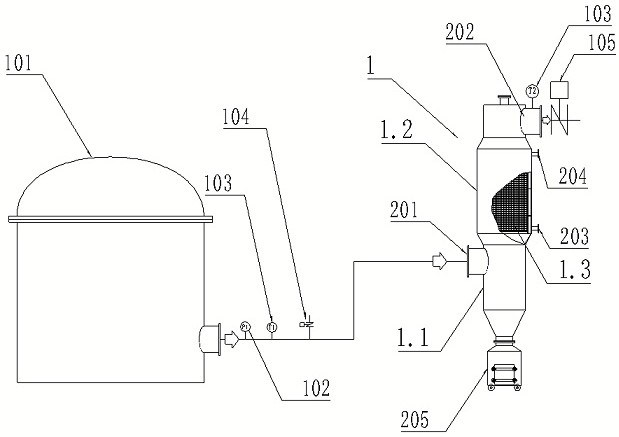
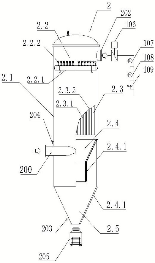
[0053] see Figure 1~4 , the invention relates to a dry mechanical vacuum system for a molten steel high vacuum refining furnace, the dry mechanical vacuum system for a molten steel high vacuum refining furnace includes a molten steel refining furnace 101 and a flue gas cooling primary filter device sequentially connected in sequence 1. The flue gas bag type fine filter device 2 and the mechanical vacuum pump group 3; the molten steel refining furnace 101 is a VD furnace, VOD furnace or RH furnace;
[0054] The flue gas cooling primary filter device 1 includes a dust removal chamber 1.1 arranged below, a heat exchange chamber 1.2 arranged above and a heat exchanger 1.3 arranged in the heat exchange chamber 1.2, and the heat exchanger 1.3 is welded Finned tube heat exchanger; the ash removal bin 1.1 and the heat exchange bin 1.2 are connected up and down; the side of the ash removal bin 1.1 is provided with a flue gas inlet 201; the top side of the heat exchange bin 1.2 is prov...
PUM
 Abstract
Description
Claims
Application Information
PatSnap Eureka turns technology decisions into work you can execute. Powered by our Innovation Knowledge Graph, it runs expert workflows across engineering, life sciences, materials and intellectual property. Get your review-ready output in minutes.


