Supercharge Your Innovation With Domain-Expert AI Agents!

Wear-resistant gauge protection tearing cutter

A wear-resistant, tearing knife technology, applied in mining equipment, earthwork drilling, tunnels, etc., can solve the problems of increased thrust, high frequency of start and stop of shield machine, high frequency of tool change, etc., and achieve the speed of delaying wear , Improve the excavation efficiency and reduce the frequency of tool change

Inactive Publication Date: 2020-11-06
CHINA CREC RAILWAY ELECTRIFICATION BUREAU GRP
View PDF6 Cites 0 Cited by
  • Summary
  • Abstract
  • Description
  • Claims
  • Application Information

AI Technical Summary

Problems solved by technology

The gauge knife is installed on the outermost side of the cutterhead to ensure the excavation diameter of the cutterhead. If the gauge knife is severely worn, the excavation diameter of the cutterhead cannot be guaranteed, and the shield shell of the shield machine will be stuck, the thrust will increase, and the segments will break , resulting in engineering accidents
Timely replacement of the gauge tearing knife can avoid such accidents, but because the existing gauge tearing knife usually uses an alloy cutter head in the cutter head, but the blade part is rubbed by the hard rocks of the formation due to the rotation of the cutter head. Rapid wear and high frequency of tool changes reduce tunnel excavation efficiency, and the high frequency of start and stop of shield machines also leads to unnecessary energy consumption

Method used


Image

  • Wear-resistant gauge protection tearing cutter
  • Wear-resistant gauge protection tearing cutter
  • Wear-resistant gauge protection tearing cutter

Examples


Embodiment 1

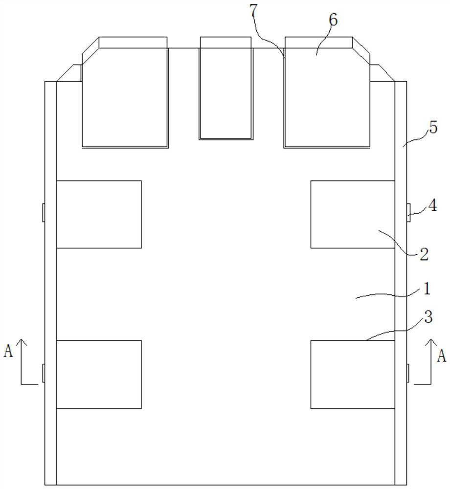
[0041] Such as figure 1 As shown, a wear-resistant gauge tearing knife includes a blade body 1 and an alloy blade 6 fixed on the head of the blade body 1;

[0042] Two grooves 3 are respectively opened on the upper surface of the blade 1 and at positions close to both sides of the blade 1, and the two grooves 3 on the same side are respectively distributed at the front and rear of the side, and the grooves 3 are adjacent to the corresponding side walls of the blade 1. An alloy block 2 is fixed in the groove 3, and the upper surface of the alloy block 2 is flush with the upper surface of the blade 1;

[0043] Both sides of the blade 1 are respectively provided with alloy plates 5 detachably connected to the corresponding alloy blocks 2. The length direction of the alloy plate 5 extends along the length direction of the side wall of the blade 1, and is close to the corresponding side wall of the blade 1. The upper edge of the plate 5 is flush with the upper surface of the blade 1 and...

Embodiment 2

[0051] The difference from Example 1 is:

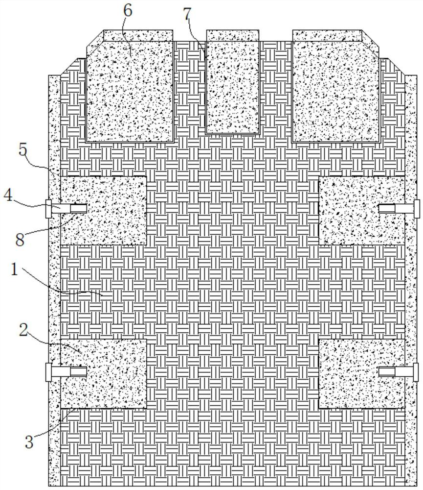
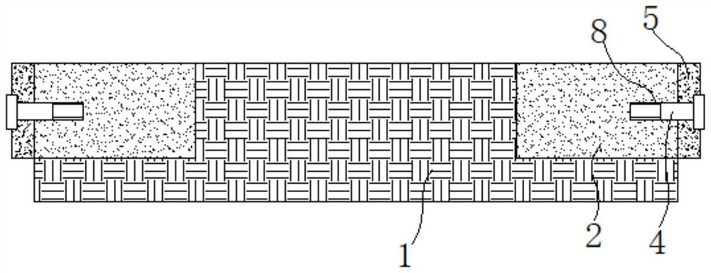
[0052] Such as Figure 4 with Image 6 As shown, the upper edge of the alloy plate 5 is integrally formed with an alloy wing plate 9 that extends horizontally to the blade 1, and the lower surface of the alloy wing plate 9 abuts against the upper surface of the blade 1.

[0053] Specific, such as Figure 5 with Figure 7 As shown, the lower surface of the alloy wing plate 9 is integrally formed with a plurality of alloy positioning posts 10, the upper surface of the blade 1 is provided with positioning grooves corresponding to the alloy positioning posts 10, and the alloy positioning posts 10 are inserted into the corresponding positioning grooves, and The inner wall of the positioning groove is used for clearance fit.

[0054] Preferably, the alloy positioning column 10 has a square column structure, and the positioning groove has a square groove 3 structure matching the shape and size of the alloy positioning column 10.

[0055] Preferably...


PUM

PropertyMeasurementUnit
Thicknessaaaaaaaaaa
Groove depthaaaaaaaaaa

Abstract

The invention discloses a wear-resisting gauge protection tearing cutter. The wear-resisting gauge protection tearing cutter comprises a cutter body and an alloy cutter head fixed to the head of the cutter body; at least one groove is formed in the upper surface of the cutter body and the positions close to the two sides of the cutter body correspondingly; the sides, close to the corresponding side walls of the cutter body, of the grooves are open; alloy blocks are fixedly arranged in the grooves, and the upper surfaces of the alloy blocks are flush with the upper surface of the cutter body; alloy plates detachably connected with the corresponding alloy blocks are arranged on the two sides of the cutter body correspondingly, the length directions of the alloy plates extend in the length direction of the side walls of the cutter body and are tightly attached to the corresponding side walls of the cutter body; and the upper edges of the alloy plates are flush with the upper surface of the cutter body, and the width of the alloy plates is less than or equal to the thickness of the cutter body. The wear-resisting gauge protection tearing cutter is resistant to abrasion and long in service life, the cutter changing frequency can be reduced, the tunneling excavation efficiency is improved, and unnecessary energy consumption caused by frequent starting and stopping of the shield tunneling machine is avoided.

Description

Technical field [0001] The invention relates to an earth pressure balance shield machine tool, in particular to a wear-resistant gauge tearing knife. Background technique [0002] In the process of tunnel excavation using the earth pressure balance shield machine, the geology is found to be a sand and pebble stratum, with a large amount of pebbles, a large particle size and mixed with sand. This stratum leads to severe tool wear, especially for gauges. Tearing knife. The gauge knife is installed on the outermost side of the cutter head to ensure the excavation diameter of the cutter head. If the gauge knife is severely worn, the excavation diameter of the cutter head cannot be guaranteed, and the shield shell of the shield machine will be stuck, the thrust will increase, and the tube segment will be broken. , Resulting in engineering accidents. Although timely replacement of the gauge tearing knife can avoid such accidents, and because the existing gauge tearing knife usually u...

Claims


Application Information

Patent Timeline
IPC IPC(8): E21D9/08
CPCE21D9/08
Inventor 李清宪祁宝成王建伟吉帅科王润超史强康福常李丛户鹏胡博姜洪朋吴磊刘磊何志军
Owner CHINA CREC RAILWAY ELECTRIFICATION BUREAU GRP
Features
  • R&D
  • Intellectual Property
  • Life Sciences
  • Materials
  • Tech Scout
  • Unparalleled Data Quality
  • Higher Quality Content
  • 60% Fewer Hallucinations
Learn More