Novel non-combustible floor heating system

A new type of floor heating technology, applied in the field of floor heating, can solve problems such as uneven heating of heating cables, low temperature of heating cables, and potential fire safety hazards, and achieve the effects of eliminating potential safety hazards, reducing heating efficiency, and high safety performance

Pending Publication Date: 2020-11-06
福建久信科技有限公司
View PDF1 Cites 3 Cited by
  • Summary
  • Abstract
  • Description
  • Claims
  • Application Information

AI Technical Summary

Problems solved by technology

The inventor pointed out that the disadvantage of laying heating cables on the ground (main heating cable, auxiliary heating power) is that the heat generation of the heating cables is uneven, especially when the main heating cables and auxiliary heating power are laid in a circuitous manner, the distance between adjacent heating cables is different. , the temperature on the ground is slightly different, specifically including the following situations: (1) The temperature is high where the heating cables are densely laid, and the temperature is low where the heating cables are sparsely laid; (2) The temperature directly above the heating cables is high, and the adjacent heating cables (3) There is another situation where thermal insulation materials (cloths, sofas, etc.) are placed on the ground, and the temperature will continue to rise at this position, which poses a fire safety hazard

Method used


Image

  • Novel non-combustible floor heating system
  • Novel non-combustible floor heating system
  • Novel non-combustible floor heating system

Examples


Embodiment Construction

[0016] The present invention will be further described in conjunction with the accompanying drawings and specific embodiments.

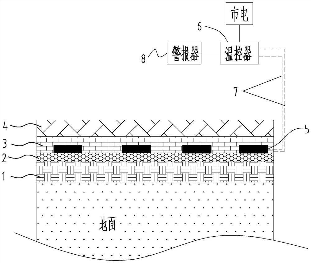
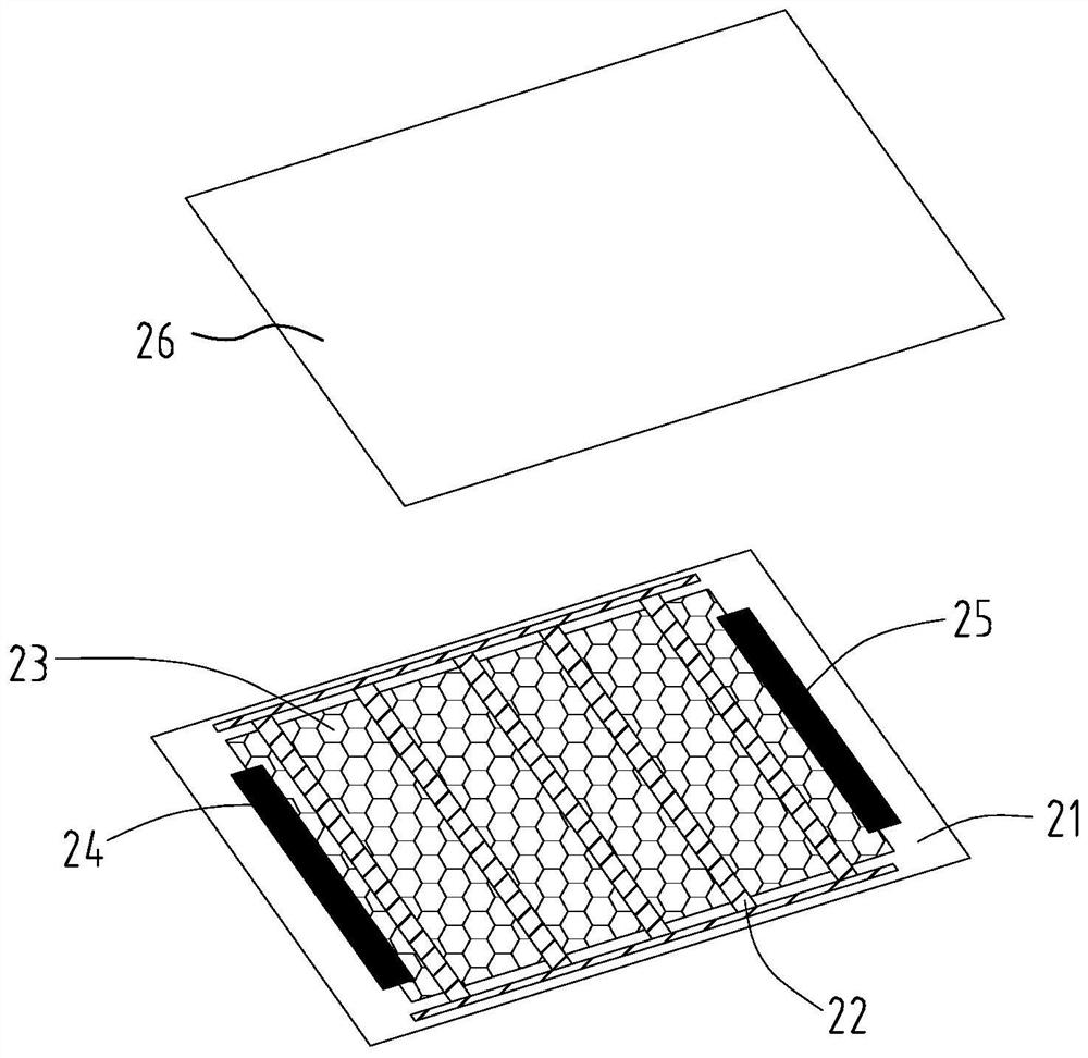
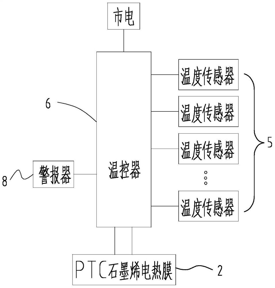
[0017] refer to figure 1 , figure 2 and image 3 , this embodiment provides a new type of non-combustible floor heating system, including a thermostat 6, a plurality of temperature sensors 5 ( figure 1 Only four temperature sensors 5), alarm 8, and flame-retardant insulation layer 1, PTC graphene electrothermal film 2, thermally conductive flame-retardant cement mortar layer 3 and ground decoration layer are arranged on the ground sequentially from bottom to top. 4. A flame-retardant cable 7 is also buried between the flame-retardant insulation layer 1 and the thermally conductive flame-retardant cement mortar layer 3, and the temperature sensors 5 are evenly and equally spaced between the PTC graphene electrothermal film 2 and the thermally conductive Between fire-retardant cement mortar layers 3. In this specific embodiment, the flame retardan...


PUM

PropertyMeasurementUnit
thicknessaaaaaaaaaa

Abstract

The invention relates to a novel non-combustible floor heating system which comprises a temperature controller as well as an anti-flaming heat preservation layer, a PTC graphene electro-thermal film,a heat conducting anti-flaming cement mortar layer and a ground decoration layer which are successively disposed on the ground, wherein an anti-flaming cable is also embedded between the anti-flamingheat preservation layer and the heat conducting anti-flaming cement mortar layer; the PTC graphene electro-thermal film comprises a lower anti-flaming insulation heat conducting layer and an upper anti-flaming insulation heat conducting layer which are mutually composited, a PTC graphene heat emission oil ink layer is printed on the lower anti-flaming insulation heat conducting layer, and electricconducting sheets are disposed on two ends of the PTC graphene heat emission oil ink layer respectively; and the electric conducting sheets of the PTC graphene electro-thermal film are electrically connected to the temperature controller by the anti-flaming cable, and the temperature controller is connected to mains supply. The PTC graphene electro-thermal film is uniform in heat conduction and has an automatic temperature limiting characteristic, so that continuous temperature rise is avoided, and safety performance is high; and because of an anti-flaming characteristic of the anti-flaming heat preservation layer and the heat conducting anti-flaming cement mortar layer, hidden safety hazards of fire disasters are avoided.

Description

technical field [0001] The invention relates to the field of floor heating, in particular to a novel non-combustible floor heating system. Background technique [0002] Floor heating is the abbreviation of ground radiation, which uses the entire ground as a radiator to uniformly heat the entire ground through a heat medium. In terms of heat medium, it can be divided into two categories: water floor heating and electric floor heating. Compared with water floor heating, electric floor heating heats up faster (water floor heating needs to be preheated), and the temperature control is more precise and does not need to be cleaned (water floor heating generally takes 2-5 years) Need to clean the ground coil once), electric floor heating is more and more popular. [0003] The common setting method of existing electric floor heating is to lay heating cables (similar to electric heating wires) on the ground, such as the heating cable electric floor heating technology disclosed in th...

Claims


Application Information

Patent Timeline
Patent Type & Authority Applications(China)
IPC IPC(8): F24D13/02F24D19/10H05B3/34
CPCF24D13/024F24D19/1096F24D2200/08H05B3/34H05B2203/01
Inventor 王诗榕王书传张秀会王海波舒丰雄
Owner 福建久信科技有限公司
Why Eureka
Try Eureka