
Entanglement source and linear damping polluted liquid drop detection device

A technology of entanglement source and pollution liquid, applied in the field of pollution source detection, can solve the problems of harsh environment of the detection device, easy loss of information, no provision, etc., and achieve the effect of rich detection information, stable parameters, and improved accuracy

Active Publication Date: 2020-11-06
SHANGHAI UNIV
View PDF6 Cites 0 Cited by
  • Summary
  • Abstract
  • Description
  • Claims
  • Application Information

AI Technical Summary

Problems solved by technology

[0002] At present, the detection device with very small interface concentration of pollutants has the problems of easy loss of information, unstable performance, and unsafe operation, and the environment required by the detection device is very harsh.
[0003] In the article Determination ofInterfacial Concentration of a Contaminated Droplet from Shape OscillationDamping, Frenchman Benjamin Lalanne discussed the mechanism of the contaminated droplet interface, and numerical simulation analyzed the decomposition of the contaminated droplet into a Legendre function mode, but did not provide a detection device that can realize the use of entanglement sources and linear system resonance elastic damping characteristics

Method used


Image

  • Entanglement source and linear damping polluted liquid drop detection device
  • Entanglement source and linear damping polluted liquid drop detection device
  • Entanglement source and linear damping polluted liquid drop detection device

Examples


Embodiment Construction

[0029] The following will clearly and completely describe the technical solutions in the embodiments of the present invention with reference to the accompanying drawings in the embodiments of the present invention. Obviously, the described embodiments are only some, not all, embodiments of the present invention. Based on the embodiments of the present invention, all other embodiments obtained by persons of ordinary skill in the art without making creative efforts belong to the protection scope of the present invention.

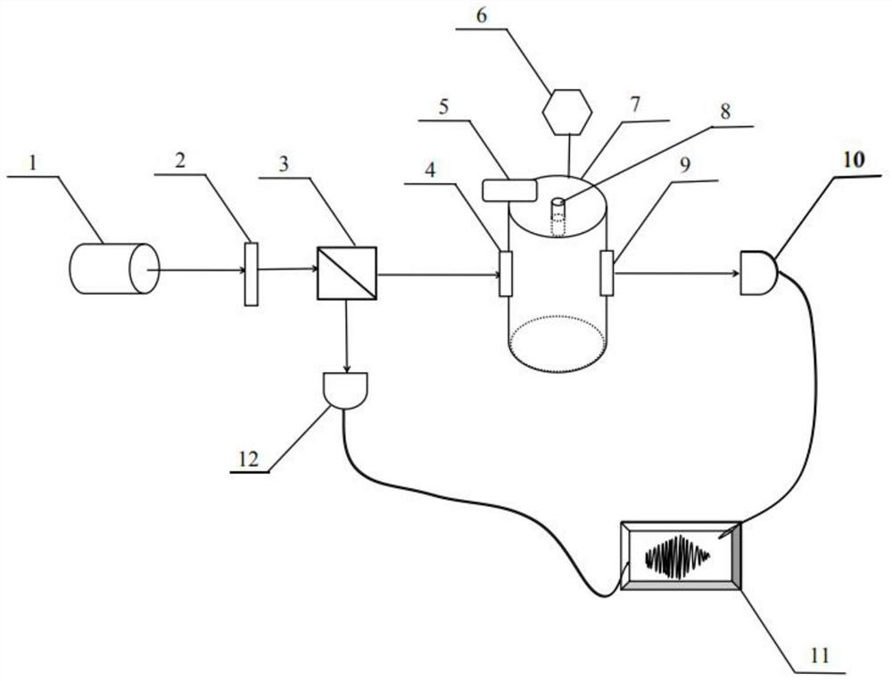
[0030] The purpose of the present invention is to provide an entanglement source and linear damping detection device for polluting droplets, which uses the entanglement source and linear system resonance elastic damping characteristics for detection, so that the detection information is richer, the detection process is more stable, and the detection accuracy is improved.

[0031] In order to make the above objects, features and advantages of the present inventi...


PUM


Abstract

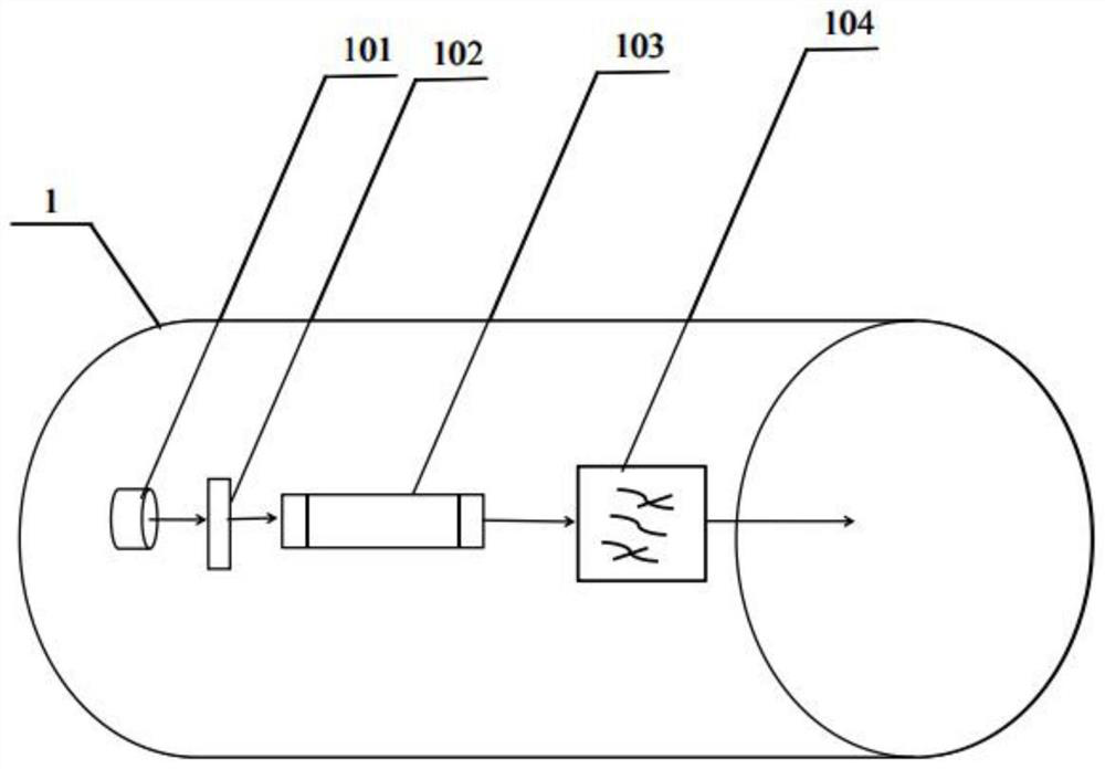
The invention relates to an entanglement source and linear damping polluted liquid drop detection device. The device comprises an entangled source emitter, a quarter-wave plate, a polarization beam splitter, a target chamber, a control linear damper, a vacuum controller, a polluted liquid drop controller and an information processor, wherein the polluted liquid drop controller is used for drippingpolluted liquid drops to be detected into the target chamber; the two sides of the target chamber are provided with a transparent incident window and a transparent emergent window respectively; the vacuum controller is used for vacuumizing the target chamber; the linear damper is controlled to input inert gas into the target chamber; an entangled photon pair emitted by the entangled source emitter sequentially passes through the quarter-wave plate and the polarization beam splitter and then is divided into two beams of light; and one beam of light enters the target chamber through the incident window, irradiates to-be-detected polluted liquid drops and then is emitted out through the emergent window; and the information processor is used for generating a coherent spectrum image accordingto the light beam carrying the detection information and emitted by the exit window and the other light beam passing through the polarizer. According to the invention, the detection information is richer, the detection process is more stable, and the detection accuracy is improved.

Description

technical field [0001] The invention relates to the technical field of pollution source detection, in particular to an entanglement source and linear damping detection device for polluted droplets. Background technique [0002] At present, detection devices with very small interface concentrations of pollutants have the problems of easy loss of information, unstable performance, and unsafe operation, and the environment required by the detection devices is very harsh. [0003] In the article Determination ofInterfacial Concentration of a Contaminated Droplet from Shape OscillationDamping, Frenchman Benjamin Lalanne discussed the mechanism of the contaminated droplet interface, and numerical simulation analyzed the decomposition of the contaminated droplet into a Legendre function mode, but does not provide a detection device that can be realized using entangled sources and linear system resonance elastic damping characteristics. Contents of the invention [0004] Based on...

Claims


Application Information

Patent Timeline
Patent Type & Authority Applications(China)
IPC IPC(8): G01N21/31G01N21/23
CPCG01N21/23G01N21/31
Inventor 吴明红金石琦雷波浦娴娟孙龙雷勇
Owner SHANGHAI UNIV
Learn More