Optical lens group, camera module and terminal

A technology of optical mirrors and lenses, applied in optics, optical components, instruments, etc., can solve the problems of reducing the total length of the lens, the thickness of the lens, etc. Effect of Small Maximum Diameter

Pending Publication Date: 2020-11-06
JIANGXI JINGCHAO OPTICAL CO LTD
View PDF0 Cites 1 Cited by
  • Summary
  • Abstract
  • Description
  • Claims
  • Application Information

AI Technical Summary

Problems solved by technology

[0003] The embodiment of the present application provides an optical lens group, a camera module and a terminal, which can solve the problem that the lens is too thick, and can reduce the total length of the lens while ensuring higher image clarity, making the lens lighter and thinner

Method used


Image

  • Optical lens group, camera module and terminal
  • Optical lens group, camera module and terminal
  • Optical lens group, camera module and terminal

Examples


Embodiment 1

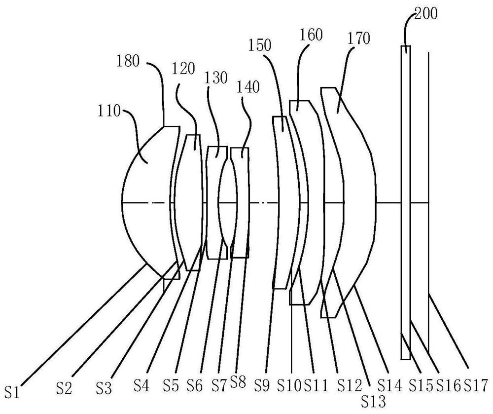
[0080] For a schematic structural diagram of the imaging optical lens group of the embodiment of the present application, see figure 1 , the optical lens group includes a diaphragm 180 (attached to the object side S1 of the first lens), a first lens 110, a second lens 120, and a third lens 130 arranged in sequence along the optical axis from the object plane to the image plane of the entire optical system , the fourth lens 140 , the fifth lens 150 , the sixth lens 160 , the seventh lens 170 and the infrared filter 200 .

[0081] The first lens 110 has a positive refractive power, the object side of the first lens 110 at the near optical axis is convex, and the image side of the first lens 110 at the near optical axis is concave. The object side of the first lens 110 at the circumference is convex, and the image side of the first lens 110 at the circumference is concave.

[0082] The second lens 120 has a positive refractive power, the object side of the second lens 120 at the...

Embodiment 2

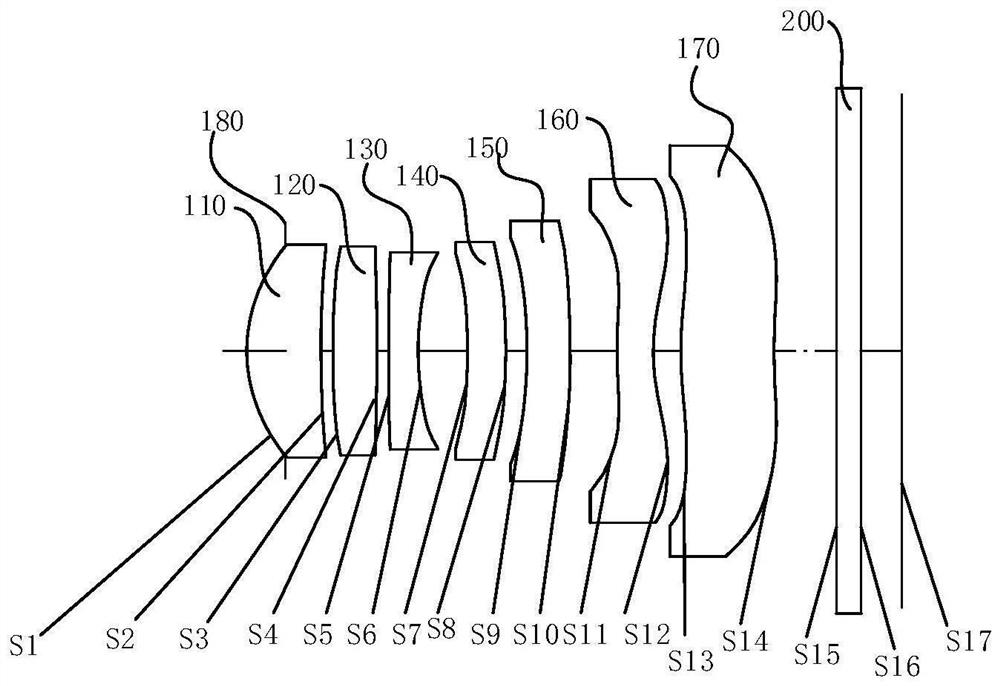
[0112] For a schematic structural diagram of the imaging optical lens group of the embodiment of the present application, see Figure 5 , the optical lens group includes a diaphragm 180 (attached to the object side S1 of the first lens), a first lens 110, a second lens 120, and a third lens 130 arranged in sequence along the optical axis from the object plane to the image plane of the entire optical system , the fourth lens 140 , the fifth lens 150 , the sixth lens 160 , the seventh lens 170 and the infrared filter 200 .

[0113] The first lens 110 has a positive refractive power, the object side of the first lens 110 at the near optical axis is convex, and the image side of the first lens 110 at the near optical axis is concave. The object side of the first lens 110 at the circumference is convex, and the image side of the first lens 110 at the circumference is concave.

[0114] The second lens 120 has a positive refractive power, the object side of the second lens 120 at th...

Embodiment 3

[0134] For a schematic structural diagram of the imaging optical lens group of the embodiment of the present application, see Figure 9 , the optical lens group includes a diaphragm 180 (attached to the object side S1 of the first lens), a first lens 110, a second lens 120, and a third lens arranged in sequence along the optical axis from the object plane to the image plane of the entire optical lens group 130 , a fourth lens 140 , a fifth lens 150 , a sixth lens 160 , a seventh lens 170 and an infrared filter 200 .

[0135] The first lens 110 has a positive refractive power, the object side of the first lens 110 at the near optical axis is convex, and the image side of the first lens 110 at the near optical axis is concave. The object side of the first lens 110 at the circumference is convex, and the image side of the first lens 110 at the circumference is concave.

[0136] The second lens 120 has a positive refractive power, the object side of the second lens 120 at the nea...


PUM


Abstract

The invention discloses an optical lens group, a camera module and a terminal. The optical lens group comprises a first lens, a second lens, a third lens, a fourth lens, a fifth lens, a sixth lens anda seventh lens which are sequentially arranged from an object plane to an image plane along an optical axis, wherein the first lens has positive refractive power, the object side surface, near the optical axis, of the first lens is a convex surface, the second lens, the third lens, the fourth lens, the fifth lens, the sixth lens and the seventh lens respectively have refractive power, the maximumeffective diameter of the image side surface of the seventh lens is Y7[2], the distance between the object side surface of the first lens and the imaging surface of the system at the optical axis isTTL, the thickness of the optical effective diameter edge of the object side surface of the seventh lens is ET[7], the focal length of the optical lens group is f, and Y7[2], TTL, ET[7] and f satisfythe following conditional expression: (Y7[2]*TTL) / (ET[7]*f) is more than or equal to 3 and less than or equal to 8. Through the arrangement, the long-focus characteristic of the optical lens group andthe overall thickness of the optical camera lens can be balanced, and the maximum diameter of the optical camera lens is reduced while the molding yield of the seventh lens is ensured.

Description

technical field [0001] The present application relates to the technical field of optical imaging, and in particular to an optical lens group, a camera module and a terminal. Background technique [0002] At present, in order to meet the needs of shooting distant scenes and shallow depth of field to highlight the main imaging objects and to match the chips with high pixels and small size, the industry has begun to focus on the research and development of lens styles with long focal lengths. Traditional cameras mounted on electronic devices use a multi-chip lens structure. Based on the same chip, in order to obtain higher image clarity, the total length of the lens will be thickened, affecting the amount of light entering the lens, making the entire lens very thick. Thereby restricting the thinning of the lens and increasing the difficulty of assembling the lens. Contents of the invention [0003] Embodiments of the present application provide an optical lens group, a camer...

Claims


Application Information

Patent Timeline
Patent Type & Authority Applications(China)
IPC IPC(8): G02B13/00G02B13/18
CPCG02B13/0045G02B13/18
Inventor 王妮妮刘彬彬李明邹海荣
Owner JIANGXI JINGCHAO OPTICAL CO LTD
Why Eureka
Try Eureka