A gantry type anchor digging robot system

A robot system and robot technology, applied in the direction of cutting machinery, slitting machinery, installation of bolts, etc., can solve problems such as time-consuming, cumbersome operation procedures, and reduction of safety passage area, so as to ensure strength and stability, and ensure The effect of supporting efficiency and shortening the empty roof distance

Active Publication Date: 2022-06-24
XIAN UNIV OF SCI & TECH
View PDF0 Cites 0 Cited by
  • Summary
  • Abstract
  • Description
  • Claims
  • Application Information

AI Technical Summary

Problems solved by technology

[0004] At present, the existing supporting equipment is mainly the supporting operation system of cantilever roadheader + single-body bolter, the supporting operation system of continuous coal mining machine + bolter and the integrated machine operation system of digging and bolting; The supporting operation system of the rod drilling rig has a low level of scientific excavation system and low mechanization capability. Many excavation processes still require manual operations. Because these processes are scattered, a lot of preparation time is required and the efficiency is low; continuous miner + bolter The supporting operation system can only be applied to double lanes, which has high requirements on geological conditions, and the operation process is cumbersome, requiring high professionalism and proficiency of the operation line operators; The area of ​​the safe passage is reduced, and when encountering an area with an unstable floor, it is easy to fall into it, and the staff need to spend a lot of time digging it out. It is suitable for areas with good geological conditions, and the actual application effect is not good.
[0005] Through the above analysis, it can be known that the factors that affect the efficiency of excavation are mainly the imbalance between excavation and support. The support in the excavation process takes a lot of time and the equipment is not fully mechanized.

Method used


Image

  • A gantry type anchor digging robot system
  • A gantry type anchor digging robot system
  • A gantry type anchor digging robot system

Examples


Embodiment Construction

[0029] The present invention will be described in detail below with reference to specific embodiments. The following examples will help those skilled in the art to further understand the present invention, but do not limit the present invention in any form. It should be noted that, for those skilled in the art, several modifications and improvements can be made without departing from the concept of the present invention. These all belong to the protection scope of the present invention.

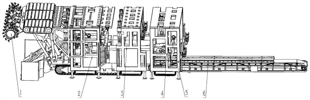
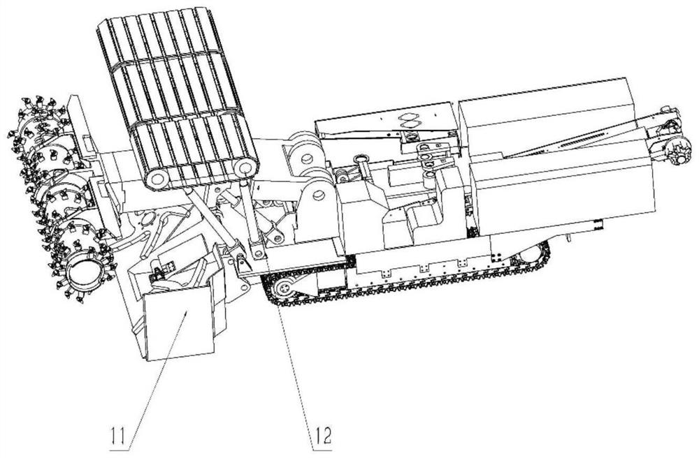
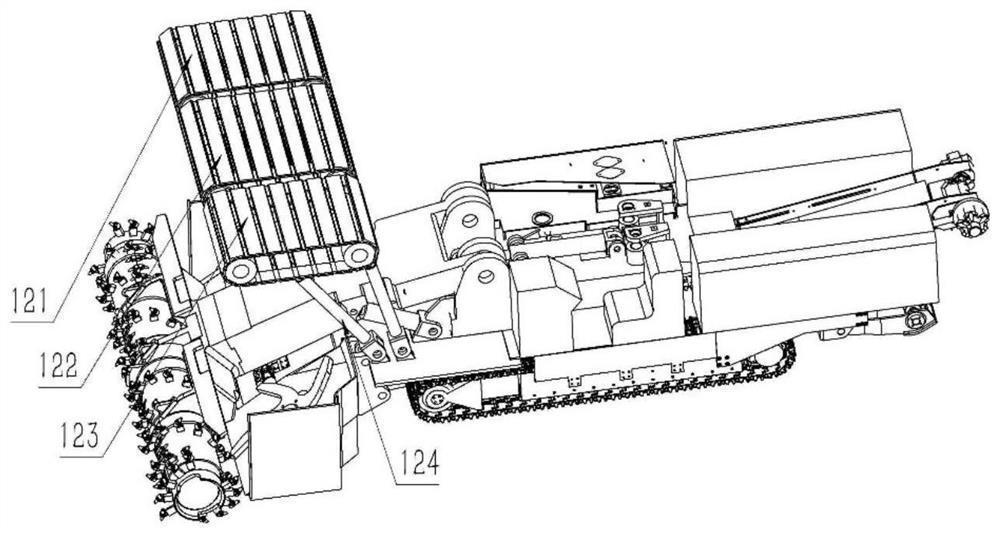
[0030] like Figure 1-Figure 2 As shown, a gantry-type anchor-digging and protecting robot system includes a cutting robot 1, a temporary support mechanism 12, an anchor-drilling robot I2, an anchor-drilling robot II3, an anchor-drilling robot III4 and a transport device 5; the cutting robot 1, the temporary support The protection mechanism 12 is located at the front of the system, the anchor drilling robot I2, the anchor drilling robot II3, the anchor drilling robot III4, the staff 5 and t...


PUM


Abstract

The present invention relates to the field of machinery, in particular to a gantry-type anchor digging robot system, including a cutting robot, a temporary support mechanism, a drilling and anchoring robot I, a drilling and anchoring robot II, a drilling and anchoring robot III, a transportation device; a cutting robot, The temporary support mechanism is located at the front of the system, and the anchor-drilling robot I, the anchor-drilling robot II, and the anchor-drilling robot III are sequentially arranged behind the cutting robot, and the anchor-drilling robot I, the anchor-drilling robot II, and the anchor-drilling robot III walk independently to ensure The system can support in time. The gantry-type anchor digging robot system of the present invention can fully adapt to the tunnel environment, effectively improve the support quality and speed, promote the tunneling efficiency, reduce the number of workers, ensure safe production, and have great significance for effectively solving the technical problems of rapid tunneling in complex geological conditions. .

Description

technical field [0001] The invention relates to the field of machinery, in particular to a gantry-type anchor-digging and protecting robot system. Background technique [0002] With the development of mining technology and equipment, the mining capacity and efficiency of coal mines have been continuously improved. However, the development of roadway excavation technology and equipment is lagging behind compared with fully mechanized mining. Coal enterprises generally have the problem of unbalanced mining ratio. The problem of imbalance is also increasingly prominent. [0003] According to the statistics of the annual report on the mechanized production of coal mines in China in recent years, in one operation cycle, the support time accounts for 1 / 2 of the total cycle time, the excavation time accounts for 1 / 3, the work preparation time and mechanical failure time account for 1 / 6, and the excavation time is fast. The problem of slow support has become a key problem affecting...

Claims


Application Information

Patent Timeline
Patent Type & Authority Patents(China)
IPC IPC(8): E21C25/66E21C25/68E21D23/04E21D20/00E21B15/00E21C29/22
CPCE21C25/66E21C25/68E21D23/0004E21D23/04E21D20/003E21B15/003E21C29/22
Inventor 马宏伟赵昊王川伟薛旭升毛清华梁林高佳晨贾泽林孙那新汪强李亚坤杨金科
Owner XIAN UNIV OF SCI & TECH
Why Eureka
Try Eureka