
Photovoltaic dimming composite glass and control system thereof

A composite glass and control system technology, applied in photovoltaic power generation, roofing, transportation and packaging, etc., can solve the problems of voltage can not be transposed, affect the electrical output of photovoltaic glass, heavy weight, etc., to avoid the effect of easy cracking

Active Publication Date: 2020-11-10
FUYAO GLASS IND GROUP CO LTD
View PDF13 Cites 11 Cited by
  • Summary
  • Abstract
  • Description
  • Claims
  • Application Information

AI Technical Summary

Problems solved by technology

In the technical solution disclosed in this utility model, the photovoltaic glass and the dimming glass are formed into an integrated structure through a hollow structure. This is obviously a glass curtain wall structure. The development direction of thin and light glass and intelligence
The laminated structure of photovoltaic glass and dimming glass will cause the dimming glass to lose its dimming characteristics due to the opacity of the photovoltaic cell itself, or the light will be lost after passing through the dimming glass, which will affect the light incident on the photovoltaic glass, thus affecting the photovoltaic performance. The electrical output of the glass; at the same time, the tinned copper strip of the photovoltaic glass is connected in series with the dimming liquid crystal film, the voltage cannot be transposed, and the dimming liquid crystal film cannot play the role of dimming

Method used


Image

  • Photovoltaic dimming composite glass and control system thereof
  • Photovoltaic dimming composite glass and control system thereof
  • Photovoltaic dimming composite glass and control system thereof

Examples


Embodiment Construction

[0034] In order to describe the technical content, the realized purpose and the effect of the present invention in detail, the present invention will be further described below in conjunction with the accompanying drawings and embodiments. Obviously, the described embodiments are only part of the embodiments of the present invention, not all of them. example.

[0035] In the present invention, the orientations or positional relationships indicated by the terms "upper", "lower", etc. are all based on the orientations or positional relationships shown in the drawings. These terms are mainly used to better describe the present invention and its embodiments, and are not used to limit the indicated devices, elements or constituents to have specific orientations, and thus should not be construed as limiting the present invention.

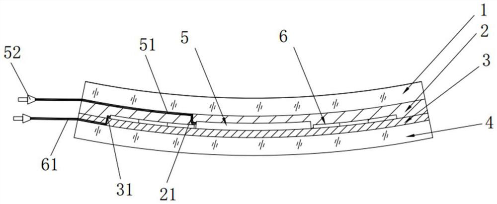
[0036] like figure 1 As shown, the present invention provides a photovoltaic dimming composite glass, including a first light-transmitting plate 1, a se...


PUM


Abstract

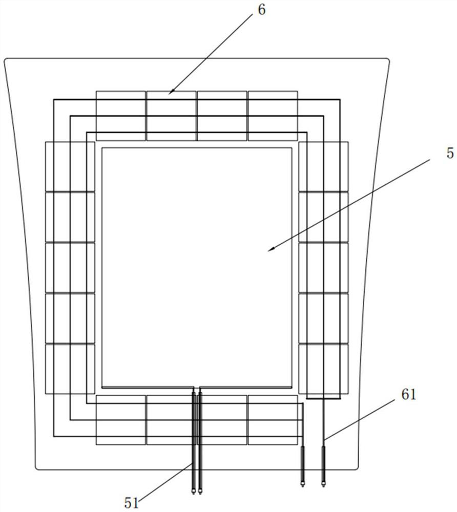
The invention provides photovoltaic dimming composite glass, and the glass comprises a first light-transmitting plate, a second light-transmitting plate, and a first bonding layer and a second bondinglayer which are positioned between the first light-transmitting plate and the second light-transmitting plate. The glass is characterized in that a dimming film is also arranged between the first bonding layer and the second bonding layer, wherein the dimming film is provided with a first leading-out wire which extends towards the edge of the glass and is led out from the edge of the glass, and the transmittance of the dimming film is changed under the driving of a power supply; a photovoltaic cell chip which is formed by connecting a plurality of independent cells in series or in parallel orin series and in parallel, wherein the photovoltaic cell chip is provided with a second leading-out wire which extends towards the edge of the glass and is led out from the edge part of the glass; the photovoltaic cell chips are arranged between the first bonding layer and the second bonding layer side by side, and the distance between the edges of the photovoltaic cell chips and the edge of thedimming film is greater than or equal to 5 mm. Daylighting and photovoltaic power generation are both considered, electricity generated by photovoltaic power generation can be directly supplied to thedimming film for use, the appearance is neat, the overall structure is simple, and implementation is easy.

Description

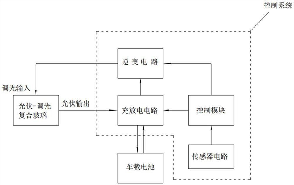
Technical field: [0001] The invention relates to the field of multifunctional photovoltaic composite products, in particular to a photovoltaic dimming composite glass and a control system thereof. Background technique: [0002] With the vigorous development of solar photovoltaic power generation technology, clean and pollution-free solar panels have been widely used in all walks of life. The earliest small-scale applications can be traced back to solar panels on artificial satellites. Nowadays, people often place solar panels on On the roof of buildings, there are even attempts to combine solar panels with car glass to form solar sunroofs. Under the development trend of new energy vehicles in the future, the application of solar panels in vehicles has broad prospects. [0003] On the other hand, the development and application of electronically controlled dimming technology on automotive glass has also made great progress, and more and more mature dimmable sunroof products ...

Claims


Application Information

Patent Timeline
Patent Type & Authority Applications(China)
IPC IPC(8): H01L31/048H01L31/054B60J3/04B60J7/00
CPCH01L31/0488H01L31/054B60J3/04B60J7/00Y02E10/52
Inventor 傅秋莲王加赋王武斌林生野毛祚水
Owner FUYAO GLASS IND GROUP CO LTD
Learn More