Turning tool structure of steel bar friction welding machine

A technology of friction welding and turning tools, which is applied in the direction of tools used in lathes, turning equipment, tool holder accessories, etc., can solve problems that affect the normal operation of steel bar welding, affect the quality of steel bar processing, and troublesome tool replacement, etc., to achieve Guarantee the economic benefits of the work, ensure the efficiency of production work, and facilitate the maintenance and replacement of work

Inactive Publication Date: 2020-11-13
绍兴市知凡机械有限公司
View PDF8 Cites 5 Cited by
  • Summary
  • Abstract
  • Description
  • Claims
  • Application Information

AI Technical Summary

Problems solved by technology

[0003] For the friction welding of steel bars during friction welding, there will be convex edges at the welding position, which need to be cut and removed with a turning tool. On the one hand, after the cutting of convex edges on the turning tool on the steel bar welding machine There will be residues, if not removed, it will affect the next cutting work, and then affect the processing quality of the steel bars. Usually, the staff wipes and removes them by hand. During this process, the high temperature of the sharp blade will have It may cause damage to the hand, which is more dangerous. On the other hand, the tool is usually welded and fixed on the telescopic rod. It is more troublesome to replace the tool later, which brings inconvenience to the work, and may affect the normal progress of the steel welding process. For this reason, the present invention proposes a kind of turning tool structure of steel bar friction welding machine for solving the above problems

Method used


Image

  • Turning tool structure of steel bar friction welding machine
  • Turning tool structure of steel bar friction welding machine
  • Turning tool structure of steel bar friction welding machine

Examples


Embodiment Construction

[0028] The technical solutions in the embodiments of the present invention will be described clearly and completely below. The embodiments of the present invention, and all other embodiments obtained by those of ordinary skill in the art without creative work, fall within the protection scope of the present invention.

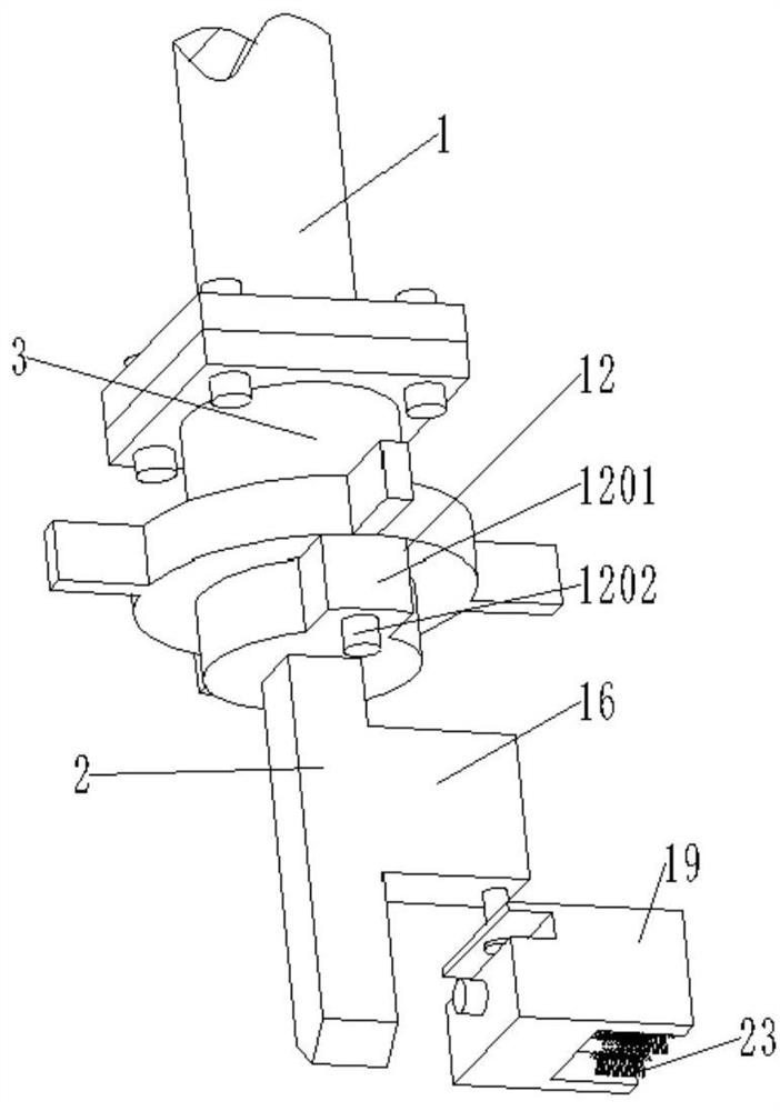
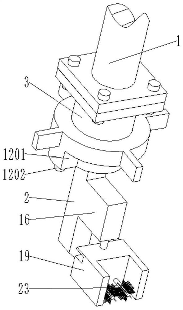
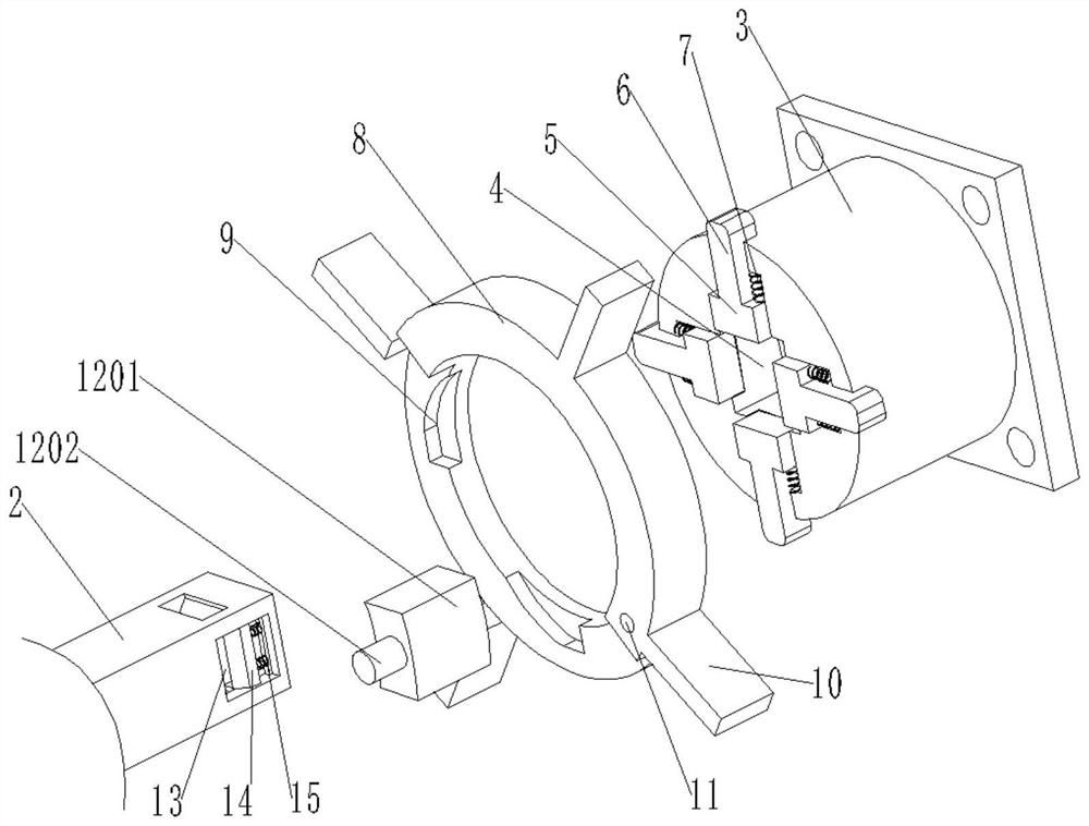
[0029] Please refer to the picture Figure 1 to Figure 7 , The present invention provides a technical solution: a turning tool structure of a steel friction welding machine, comprising a telescopic rod 1, a turning tool body 2, a connecting column 3 and a locking mechanism 12, a transmission gear set 21, and a cleaning brush 23;

[0030] One end of the telescopic rod 1 is welded with a first connecting plate, one end of the connecting column 3 is welded with a second connecting plate, and the first connecting plate and the second connecting plate are fixedly connected by bolts, and the other end of the connecting column 3 is fixed with Slot 4;

[0031] The connectin...


PUM


Abstract

The invention discloses a turning tool structure of a steel bar friction welding machine. According to the turning tool structure, a turning tool connecting structure, a fixing block, a transmission gear set and a removing brush are arranged; after a turning tool on the steel bar welding machine is subjected to convex edge cutting work, residues left on a blade can be well removed, a worker does not need to wipe the residues with hands, convenience is brought to the worker, safety guarantee is provided, the working efficiency is improved, then the working quality of steel bar machining and production is guaranteed, and the working economic benefits are guaranteed; a connecting column is connected and fixed to the turning tool, convenience is provided for later maintenance, repair and replacement work of the turning tool, rapid fixing and assembling of the turning tool are guaranteed, and the production and working efficiency is guaranteed; and in addition, a locking mechanism is arranged, and therefore the firmness and stability of connection and fixing of the turning tool can be guaranteed.

Description

Technical field [0001] The invention relates to the technical field of welding equipment, in particular to a turning tool structure of a steel friction welding machine. Background technique [0002] Friction welding machine refers to the equipment that generates heat energy during rotation, and then applies appropriate pressure to complete welding; according to the different energy input methods, friction welding machine is divided into continuous driving type and inertial type; the former is composed of fixture, transmission mechanism, and pressure mechanism , Brake device and control device; the latter is composed of clamps, transmission mechanism, flywheel, pressurizing mechanism and control device; friction welding machine: use the heat generated by the friction between the end faces of the workpiece to reach the plastic state, and then the upsetting is completed Welding method; because the chips tend to stick firmly to the cutter head when turning the workpiece, local weldin...

Claims


Application Information

Patent Timeline
Patent Type & Authority Applications(China)
IPC IPC(8): B23B27/00B23B25/00B23Q11/00
CPCB23B27/00B23B25/00B23Q11/0042
Inventor 姚超坤
Owner 绍兴市知凡机械有限公司
Why Eureka
Try Eureka