Wastewater treatment device

A wastewater treatment and reaction box technology, which is applied in multi-stage water treatment, water/sewage treatment, degassed water/sewage treatment, etc., can solve the problem of low purification efficiency of wastewater treatment equipment, low purification efficiency, and unfavorable use by people, etc. problem, to achieve the effect of simple structure, ensuring mixing efficiency, and preventing clogging

Inactive Publication Date: 2020-11-13
吴科文
View PDF7 Cites 1 Cited by
  • Summary
  • Abstract
  • Description
  • Claims
  • Application Information

AI Technical Summary

Problems solved by technology

[0003] However, the purification efficiency of existing wastewater treatment devices is not high, which is not conducive to the purification of wastewater, which makes the purification efficiency low and is not conducive to people's use.

Method used


Image

  • Wastewater treatment device
  • Wastewater treatment device
  • Wastewater treatment device

Examples


Embodiment 1

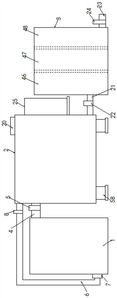
[0037] Embodiment one, such as Figure 1-11 As shown, a wastewater treatment device according to an embodiment of the present invention includes a storage tank 1, a reaction tank 2 and a purification tank 3, and the top side of the storage tank 1 is connected to the reaction tank 2 through a connecting pipe 2 4. One side of the top is fixed, and a valve two 5 is fixed on the connecting pipe two 4, and the bottom of the side of the storage tank 1 away from the connecting pipe two 4 is connected to the top of the reaction box 2 through a connecting pipe one 6 , the connecting pipe-6 is connected with the storage tank 1 through a water pump 7, the end of the connecting pipe-6 close to the reaction tank 2 is fixed with a valve-8, and the inner top of the storage tank 1 is fixed with Chute one 9, in the described chute one 9, slide and be connected with the slide plate 10 that is matched with described chute one 9, the bottom end of described slide plate 10 is fixed with electric t...

Embodiment 2

[0038] Embodiment two, such as figure 1 and 9 As shown, the inside of the purification box 3 is fixed with activated carbon adsorption layer 46, photocatalyst sterilization layer 47 and purification layer 48 successively near the side of the reaction box 2; The bar is connected with the side wall of the storage box 1; the activated carbon adsorption layer 46 arranged in turn through the purification box 3 can adsorb the substances in the sewage, and the photocatalyst sterilization layer 47 can be sterilized simultaneously, and the purification layer 48 can be used for further cleaning. purification treatment.

Embodiment 3

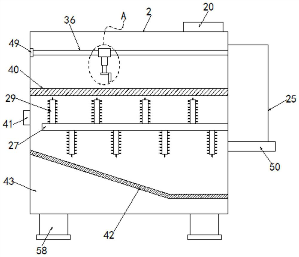
[0039] Embodiment three, such as figure 2 and 5 As shown, the end of the threaded rod one 36 away from the pulley two 35 is fixed in the inside of the reaction box 2 through a fixed sleeve three 49, and the threaded rod one 36 and the fixed sleeve three 49 are passed through a bearing Connection; the bottom of the fixed box 25 is fixed on the outer side of the reaction box 2 by the support plate two 50, and the bottom end of the motor one 26 is fixed on the inside of the fixed box 25 by the support plate one 51 Bottom: Threaded rod-36 can be fixed more stably and firmly in the inside of reaction box 2 by fixing sleeve three 49, and bearing can facilitate the rotation of threaded rod-36 simultaneously.


PUM


Abstract

The invention discloses a wastewater treatment device. The wastewater treatment device comprises a storage box, a reaction box and a purification box; one side edge of the top end of the storage box is fixed with one side edge of the top of the reaction box through a connecting pipe II; a valve II is fixed on the connecting pipe II; the bottom of one side, away from the connecting pipe II, of thestorage box is connected with the top end of the reaction box through a connecting pipe I; the connecting pipe I is connected with the storage box through a water pump; a valve I is fixed at one end,close to the reaction box, of the connecting pipe I; and a sliding groove I is fixed to the top end in the storage box. A sliding plate matched with the sliding groove I is connected into the first sliding groove in a sliding mode. An electric telescopic rod II is fixed at the bottom end of the sliding plate; an extrusion plate is fixed at the bottom end of the electric telescopic rod II; and a filter plate II is connected to the position, located below the extrusion plate, in the storage box, a sliding sleeve II is fixed to one side of the middle of the bottom end of the filter plate II and slidably connected to the outer side of a threaded rod II, and one end of the threaded rod II penetrates through the storage box, extends to the outer side of the storage box, and is connected with theoutput shaft of a motor II.

Description

technical field [0001] The invention relates to the technical field of wastewater treatment, in particular to a wastewater treatment device. Background technique [0002] Chemical waste water refers to the waste water, sewage and waste liquid produced in the process of industrial production, which contains industrial production materials, intermediate products and products lost with chemicals, and pollutants produced in the production process. With the rapid development of industry, the waste water The types and quantities are increasing rapidly, and the pollution of wastewater is becoming more and more extensive and serious, threatening human health and safety. Therefore, for the protection of the environment, the treatment of industrial wastewater is more important than the treatment of urban sewage agents. For this series of wastewater, If it is not treated in time and is discharged directly, the damage to the surrounding environment can be small or large, and it will als...

Claims


Application Information

Patent Timeline
Patent Type & Authority Applications(China)
IPC IPC(8): C02F9/08
CPCC02F9/00C02F1/001C02F1/00C02F1/283C02F1/30C02F1/20C02F2301/08C02F2303/20
Inventor 不公告发明人
Owner 吴科文
Why Eureka
Try Eureka