
Optical path fault detection device and detection method of fiber laser

A fiber laser and fault detection technology, which is applied to lasers, laser parts, phonon exciters, etc., can solve the problems of detection system misjudgment, optical fiber fluctuations, and the location of optical path faults that cannot accurately locate the laser power, so as to avoid missed alarms Or false alarm, reduce the effect of damage

Pending Publication Date: 2020-11-13
HFB PHOTONICS CO LTD
View PDF0 Cites 3 Cited by
  • Summary
  • Abstract
  • Description
  • Claims
  • Application Information

AI Technical Summary

Problems solved by technology

[0006] In order to solve technical problems such as the inability to accurately locate the location of the path failure when the optical path of the fiber laser fails and the slight fluctuations in laser power or light leakage from the optical fiber can easily cause misjudgment in the detection system, the present invention provides an optical path fault detection device and detection method for a fiber laser. The device is a device that can quickly capture the fault information of the fiber laser optical path, has a memory function, and can quickly locate the fault of the faulty optical path

Method used


Image

  • Optical path fault detection device and detection method of fiber laser
  • Optical path fault detection device and detection method of fiber laser
  • Optical path fault detection device and detection method of fiber laser

Examples


Embodiment Construction

[0023] In order to make the objectives, technical solutions and advantages of the present invention clearer, the following further describes the present invention in detail with reference to the accompanying drawings and embodiments. It should be understood that the specific embodiments described here are only used to explain the present invention and not to limit the present invention, that is, the described embodiments are only a part of the embodiments of the present invention, rather than all the embodiments.

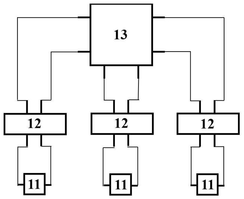
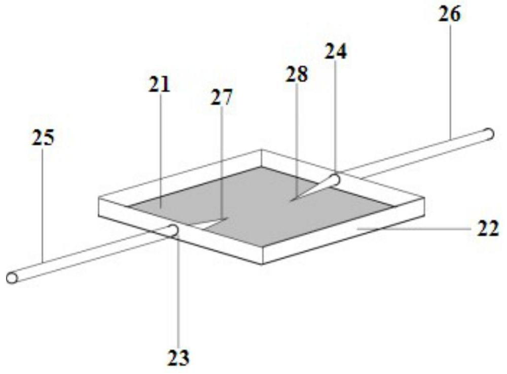
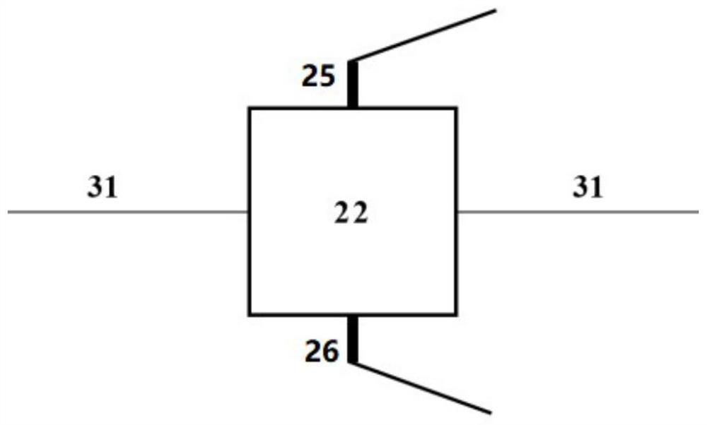
[0024] Such as figure 1 As shown, the fiber laser optical path fault detection device provided by the present invention is composed of an optical sensor module 11, a power supply module 12, and a main control chip 13. The power module 12 and the light sensor module 11 are arranged in a pair. The power module 12 is used in the device to apply electrical signals to the light sensor module 11, and at the same time transmit the level signal between the two electrodes of the...


PUM


Abstract

The invention relates to an optical path fault detection device and detection method of a fiber laser. The detection device is mainly composed of an optical sensing module, a power supply module and amain control chip. The main control chip is internally provided with an optical detection judgment program, the main body of the optical sensing module is an insulating sealed box, the box contains aphotosensitive material, and the photosensitive material has the characteristics of extremely low conductivity before exposure and instantaneous increase of conductivity after exposure. The power supply module applies an electric signal to the optical sensing module and transmits a level signal between two electrodes of the optical sensing module to the main control chip at the same time, and themain control chip judges the state of the optical sensing module according to the read level so as to judge whether an optical path is abnormal or not. The device is helpful for quickly judging the fault position of the optical path under the condition of not damaging the whole structure of the fiber laser, so that the reason of the optical path fault can be accurately positioned.

Description

Technical field [0001] The invention belongs to the technical field of optical fibers and lasers, and particularly relates to an optical path fault detection device and a detection method of an optical fiber laser. Background technique [0002] Fiber lasers are a new generation of high-energy light sources that are widely used. The output power of fiber lasers is increasing day by day. At the same time, the higher and higher output power makes the pressure and risk of the optical system increase. In particular, the aging of the laser itself and the existence of internal and external factors such as harsh application environment have increased the risk of laser optical path failure. Therefore, for the laser optical system, quickly capturing the fault information helps to protect the laser optical path to the greatest extent and reduce the damage to the optical path. For the laser optical system that has failed, it is possible to accurately locate the fault location. It helps to a...

Claims


Application Information

Patent Timeline
Patent Type & Authority Applications(China)
IPC IPC(8): G01J1/42G01M11/02H01S3/067
CPCG01J1/42G01M11/02H01S3/067
Inventor 房强史伟许阳赵一柱
Owner HFB PHOTONICS CO LTD
Learn More