Water circulation loop system

A technology of water circulation loop and container, applied in the field of water circulation loop system, can solve the problems of reduced heat exchange efficiency, component damage, rust, etc., and achieve the effect of inhibiting rolling up and inhibiting the increase of pressure loss

Active Publication Date: 2022-05-06
MITSUBISHI ELECTRIC CORP
View PDF22 Cites 0 Cited by
  • Summary
  • Abstract
  • Description
  • Claims
  • Application Information

AI Technical Summary

Problems solved by technology

If iron parts are connected to a product with a circulation circuit including a water heat exchanger, the dissolved oxygen in the circulation water acts as an oxidizing agent, causing an oxidation reaction and sometimes rusting
In addition, metal powder may remain in the flow path when constructing a product with a circulation circuit including a water heat exchanger
[0005] In this way, if there are foreign substances such as rust and metal powder in the water circulation circuit, they may adhere to the heat exchanger and reduce the heat exchange efficiency, or cause damage to the components in the water circulation circuit.

Method used


Image

  • Water circulation loop system
  • Water circulation loop system
  • Water circulation loop system

Examples


Embodiment approach 1

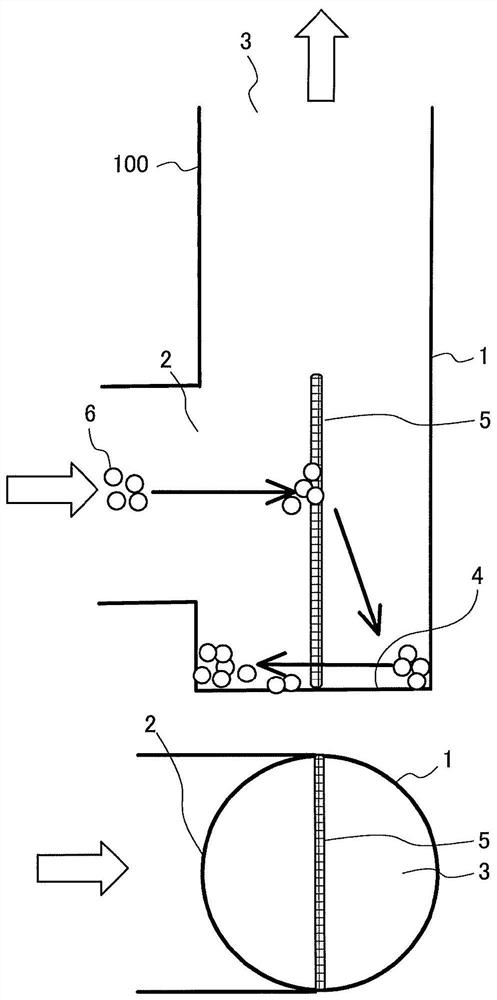
[0046] figure 1 It is a schematic diagram of a cross section in a vertical direction and a schematic diagram of a planar view of the foreign matter trapping device 100 according to Embodiment 1 of the present invention. It should be noted that, in figure 1 In , the black arrow indicates the movement of the foreign matter 6 .

[0047] Such as figure 1 As shown, the foreign matter trapping device 100 according to Embodiment 1 includes a hollow cylindrical container portion 1 constituting an outer contour. It should be noted that, in figure 1 In , the four corners of the container part 1 are each a right angle, but it is not limited thereto. The corners of the container portion 1 can also be shaped with rounded corners respectively, as will be described later. Figure 4 ~ Figure 23 is also the same.

[0048] An inlet portion 2 through which water flows into the container portion 1 is provided on a side surface of the container portion 1 . On the top of the container part 1...

Embodiment approach 2

[0062] Hereinafter, Embodiment 2 of the present invention will be described, but the description of parts overlapping with Embodiment 1 will be omitted, and the same parts as Embodiment 1 or corresponding parts will be given the same reference numerals.

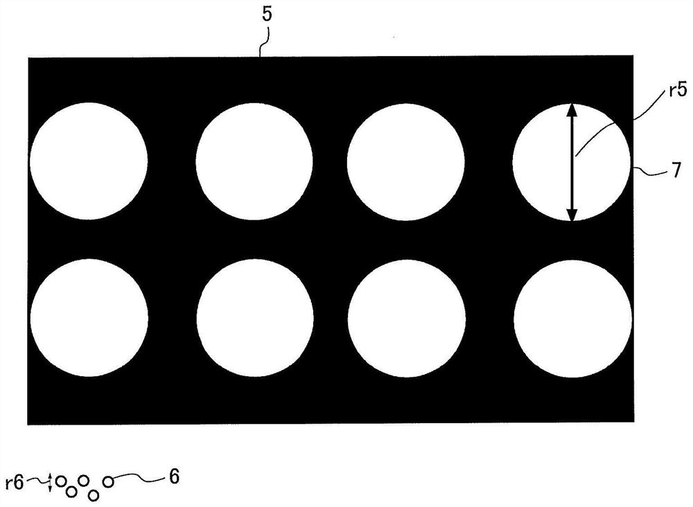
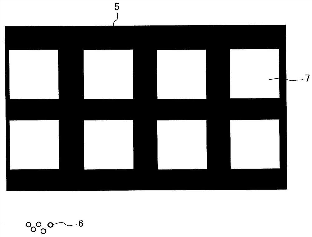
[0063] figure 2 It is an enlarged schematic diagram of the surface structure of the net 5 of the foreign matter trap 100 according to Embodiment 2 of the present invention. image 3 It is an enlarged schematic diagram of the surface structure of a modified example of the net 5 of the foreign matter trapping device according to Embodiment 2 of the present invention.

[0064] In order to exhibit the effect of settling the foreign matter 6 described in Embodiment 1, the average opening diameter of the mesh 5 may be made larger than the average particle diameter of the foreign matter 6 to be captured. It should be noted that the average opening diameter mentioned here means that the figure 2 The value obtained from the arithm...

Embodiment approach 3

[0071] Hereinafter, Embodiment 3 of the present invention will be described, but the description of parts overlapping with Embodiments 1 and 2 will be omitted, and the same or corresponding parts as Embodiments 1 and 2 will be given the same reference numerals.

[0072] Figure 4 It is a schematic diagram of a vertical cross-section and a schematic diagram of a planar view of the foreign matter trap 101 according to Embodiment 3 of the present invention. It should be noted that, in Figure 4 In , hollow arrows indicate the flow of water, and black arrows indicate the movement of foreign matter 6 .

[0073] Such as Figure 4 As shown, by making the inner diameter r1 of the container part 1 larger than the opening diameter r2 of the inlet part 2, the trapping performance of the foreign matter trapping device 101 can be improved. Such a structure has the effect of promoting the gravitational settling of the foreign matter 6 by reducing the flow velocity at the trapping portion...


PUM

PropertyMeasurementUnit
particle sizeaaaaaaaaaa

Abstract

The foreign matter capture device includes: a container part; an inlet part provided on the side of the container part to allow water to flow into the container part; an outlet part arranged above the inlet part to allow water to flow out of the container part; The position is separated from the inlet part, and the net that blocks the flow of water flowing into the container part; and the bottom of the container part that is arranged at a lower position than the inlet part, catches the water blocked by the mesh by the action of gravity. Catching part for foreign matter contained in water.

Description

technical field [0001] The present invention relates to a water circulation circuit system for capturing foreign matter contained in water. Background technique [0002] Heat exchangers are an essential technology for air conditioning / refrigeration and heating equipment. In nature, when a temperature difference is created between two fluids in proximity, heat transfer along a temperature gradient occurs. It should be noted that the fluid in this case refers to liquid and gas. Heat exchangers are designed to use this heat transfer to heat or cool any fluid. [0003] The heat exchanger prevents the mixing of fluids by sandwiching a metal with high thermal conductivity between two fluids as a heat transfer surface, and realizes efficient heat exchange. There are many types of heat exchangers, such as multi-tube type, coil type, double-tube type, plate type, spiral type, etc. The fluid for heat exchange is generally called heat medium or refrigerant, and fluorocarbons, ammon...

Claims


Application Information

Patent Timeline
Patent Type & Authority Patents(China)
IPC IPC(8): B01D21/02B01D21/28
CPCB01D21/02B01D21/24B01D21/009B01D21/0012B01D21/2494B01D2221/02F24D19/0092
Inventor 饭岛茂执行和浩野田清治吉田纯铃木一隆
Owner MITSUBISHI ELECTRIC CORP
Why Eureka
Try Eureka