
Balloon dilatation type support and taking-out device thereof

An expandable, balloon technology, applied in the field of medical devices, can solve the problems of easy deformation, limited application of small diameter parts, large overall diameter, etc.

Active Publication Date: 2020-11-17
SHENZHEN PEOPLES HOSPITAL
View PDF11 Cites 0 Cited by
  • Summary
  • Abstract
  • Description
  • Claims
  • Application Information

AI Technical Summary

Problems solved by technology

[0007] The technical problem to be solved by the present invention is that the existing balloon-expandable stent mainly relies on braided mesh as the support to play a supporting role, and is easily deformed; Large, which limits the application in smaller diameter parts

Method used


Image

  • Balloon dilatation type support and taking-out device thereof
  • Balloon dilatation type support and taking-out device thereof
  • Balloon dilatation type support and taking-out device thereof

Examples


Embodiment 1

[0041] Such as figure 1 As shown, a balloon-expandable stent includes a catheter 1, a balloon 2 arranged at one end of the catheter 1, a connecting tube 4 arranged at the other end of the catheter 1, and an interface 5; the stent body 3 can be flexibly socketed At the junction of balloon 2 and catheter 1;

[0042] Wherein, the catheter 1 communicates with the inside of the balloon 2, and the balloon is made of elastic materials such as rubber, such as figure 1 As shown, when the balloon is not inflated, the stent body 3 is sleeved at the joint between the balloon 2 and the catheter 1, and the lower end of the balloon has an irregular circular frustum structure, which is close to and wraps the top of the stent body. The diameter of the entire device is the balloon The diameter is reduced by at least 30% compared with conventional balloon-expandable stents, and can pass through thinner and narrower blood vessels; when blowing into the balloon 2, the balloon 2 expands, such as ...

Embodiment 2

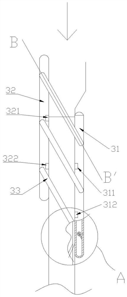
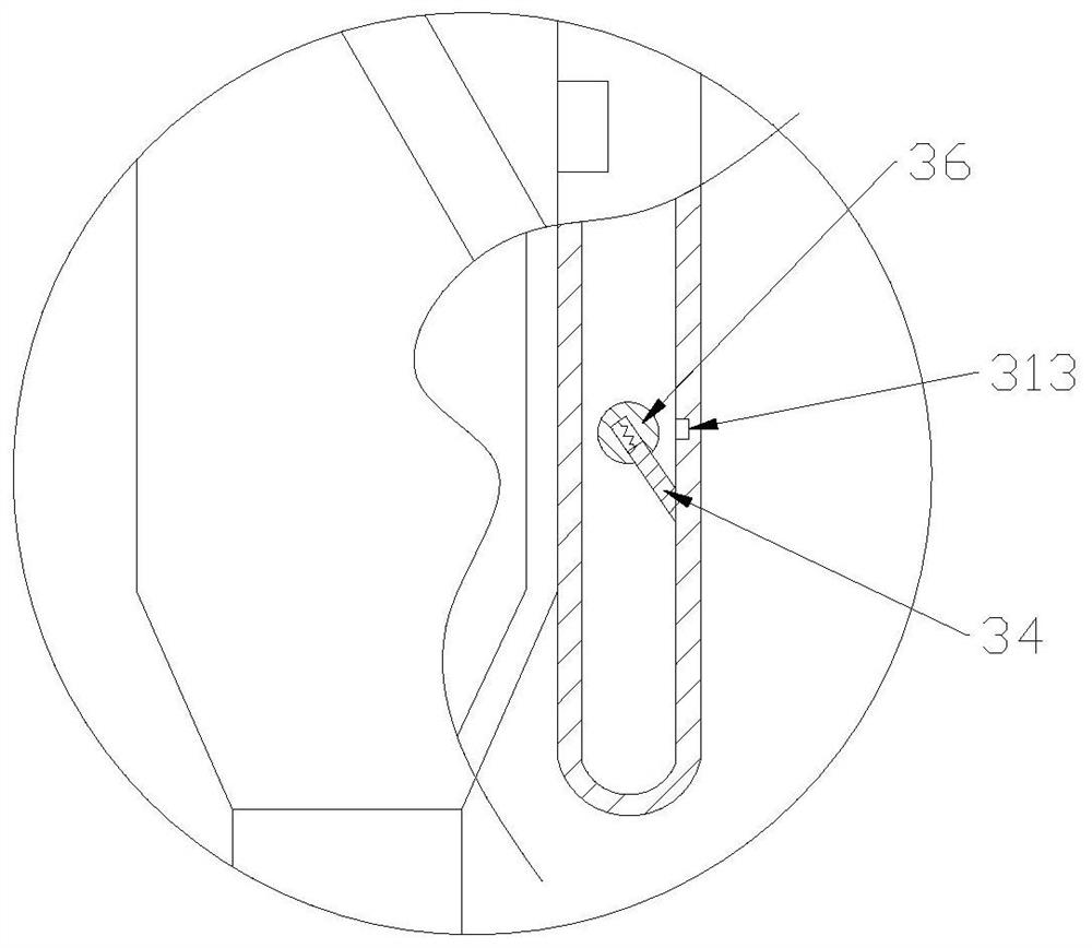
[0048] Further, such as image 3 and Figure 5 As shown, a connecting ball 36 is arranged in the connection between the first connecting rod 31 and the elastic rod 33, and the connecting parts 331 of the elastic rod are respectively fixedly connected with the corresponding connecting ball 36; the connecting ball 36 is provided with a spring 35. One end of the spring 35 is fixed in the connecting ball, and the other end is fixed to the buckle rod 34. The bayonet rod 34 extends to the outside of the connecting ball and conflicts with the inner wall of the first connecting rod 31; One side of the first connecting rod 31 is provided with several grooves 313, the grooves and the connecting balls are located on the same horizontal plane, and are formed by indenting radially outward from the inner surface of the first connecting rod 31; when the connecting part 331 rotates, it drives the connecting balls to rotate, thereby The buckle rod rotates and compresses the spring. When the e...

Embodiment 3

[0051] Further, the lower end of the balloon 2 is provided with a partition 22, and the partition is divided into two parts from the center, one upper surface is coated with magnetic material, and the end is hinged with the inner wall of the balloon through a hinge 21; the other end is The inside is coated with a magnetic material with opposite magnetic properties, and is attracted to the magnet II 24 on the inner wall of the balloon; the two partitions are connected by a hinge in the center; the hinge 21 and the magnet II 24 are symmetrically arranged; the hinge is connected to the balloon through a spring II 23 connected at the bottom. Such as Figure 6 As shown, in the state of balloon contraction, the partition is in the horizontal position, and the balloon is divided into two parts to a certain extent. As the inflation progresses, the balloon is inflated first from the position below the partition, and the second connecting rod is pushed to the top. open to Figure 7 st...


PUM


Abstract

The invention relates to the technical field of medical instruments, in particular to a balloon dilatation type support and a taking-out device thereof. The balloon dilatation type support comprises acatheter, a balloon arranged at one end of the catheter, and a connecting pipe and a connector arranged at the other end of the catheter; a support body is movably connected with the joint between the balloon and the catheter in a sleeving mode; the taking-out device comprises a catheter, a taking-out balloon arranged at one end of the catheter, and a connecting pipe and a connector arranged at the other end of the catheter; and a limiting ring is arranged at the bottom of the taking-out balloon, a plurality of protruding columns are arranged on the side face of the taking-out balloon at intervals, and the interval between the protruding columns, the interval between protruding column at lowest end and limiting ring and the interval between elastic rods are consistent. According to the balloon dilatation type support and the taking-out device thereof, by arranging the support fixed through radial magnetic force, the caliber is not prone to change, and the support is arranged below theballoon, the overall diameter of the device is further reduced, the application range is wider, a special taking-out device is arranged, operation is convenient, the working efficiency of medical staff is improved, and the pain of a patient is relieved.

Description

technical field [0001] The invention relates to the technical field of medical devices, in particular to a balloon-expandable stent and a removal device thereof. Background technique [0002] The existing treatment of diseases such as arterial stenosis and arteriovenous thrombosis mainly relies on balloon-expandable stent interventional therapy, which mainly uses a balloon catheter to reach the lesion site and then implements balloon expansion to restore access to the narrowed and blocked blood vessels. Ensure the smooth circulation of blood. However, the existing balloon-expandable stents mainly have the following problems: [0003] (1) Relying on the braided mesh as a support to play a supporting role, and the axial length of the braided mesh will be shortened when it is radially expanded, and the axial length cannot be guaranteed to be the required length, which will affect the effect of supporting blood vessels; and the braided mesh is used as When the stent is support...

Claims


Application Information

Patent Timeline
Patent Type & Authority Applications(China)
IPC IPC(8): A61F2/92A61F2/86A61M29/02
CPCA61F2/92A61F2/86A61M29/00
Inventor 不公告发明人
Owner SHENZHEN PEOPLES HOSPITAL
Learn More