
Deviation rectifying welding machine for battery assembly

A technology of battery components and welding machines, applied in welding equipment, auxiliary welding equipment, welding/cutting auxiliary equipment, etc., can solve problems such as position deviation, high equipment cost, and influence on welded products, and achieve flexibility and applicability wide, to avoid the effect of extrusion damage

Pending Publication Date: 2020-11-17
SUZHOU SHENGCHENG SOLAR EQUIP
View PDF0 Cites 7 Cited by
  • Summary
  • Abstract
  • Description
  • Claims
  • Application Information

AI Technical Summary

Problems solved by technology

[0002] During the production process of solar modules, two groups of cells need to be welded together, each group includes six strings of cells, and three kinds of welding flow bars are needed to weld these cells together, and the cells are transported to the welding place through the conveyor belt, The position of the cells will be shifted during placement and transportation, the distance between the same group of cells, the distance between two groups of cells, the horizontal level of a single cell, etc., will affect the welded product. The relevant deviation correction equipment has a complex structure, and only three motors can drive the movement and rotation in the X and Y directions separately. The distance will also change accordingly, and the cost of redesigning the equipment is high and the floor space is large. Based on the above defects and deficiencies, it is necessary to improve the existing technology and design a deviation correction welding machine for battery components.

Method used


Image

  • Deviation rectifying welding machine for battery assembly
  • Deviation rectifying welding machine for battery assembly
  • Deviation rectifying welding machine for battery assembly

Examples


Embodiment Construction

[0045] The preferred embodiments of the present invention will be described in detail below in conjunction with the accompanying drawings, so that the advantages and features of the invention can be more easily understood by those skilled in the art, so as to define the protection scope of the present invention more clearly.

[0046] see Figure 1 to Figure 21 , the embodiment of the present invention includes:

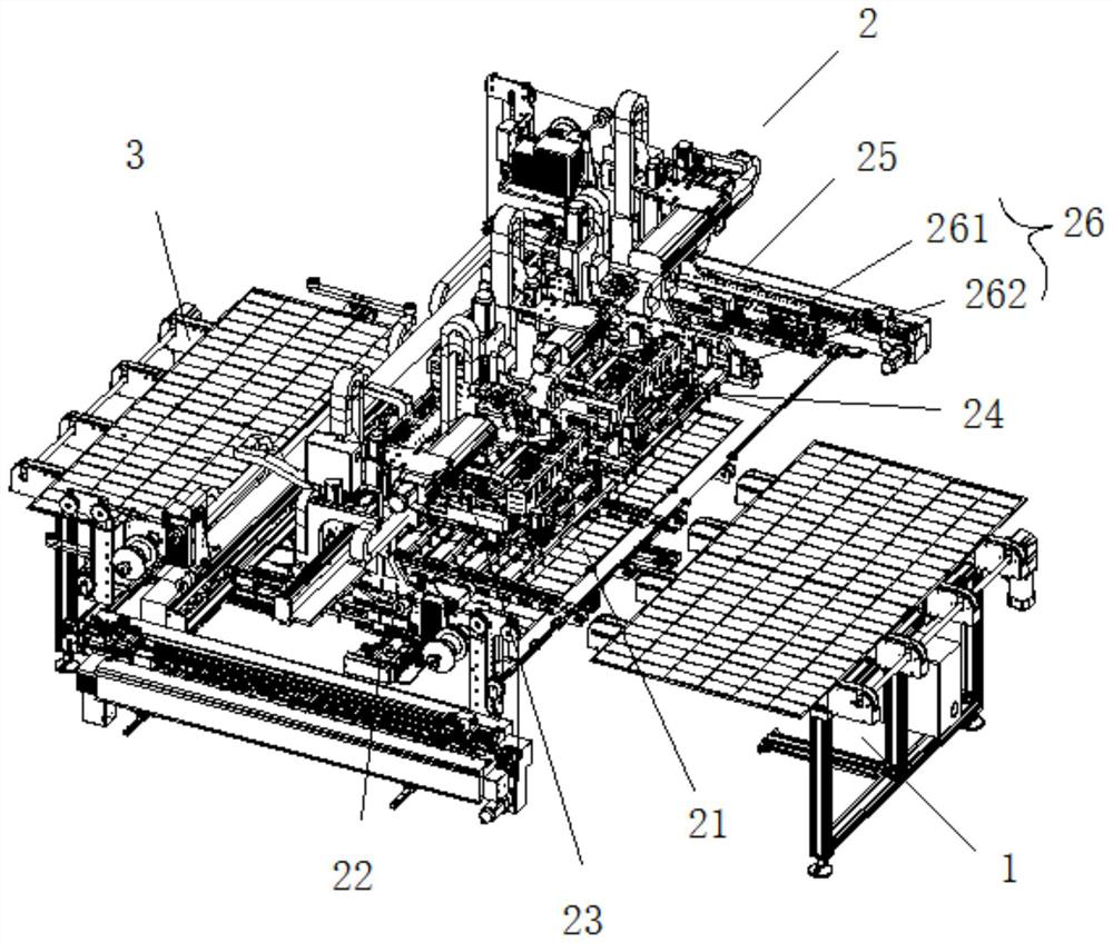
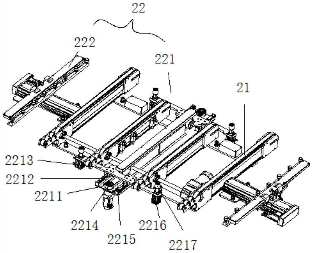
[0047] A deviation correcting welding machine for battery components, the deviation correcting welding machine for battery components includes a feed buffer conveyor belt 1, a deviation correcting welding line body 2 and a discharge conveyor belt 3 arranged in sequence, and the deviation correcting welding line body 2 includes conveying Belt 21, regularizing device 22, visual positioning device device 23, deviation correction device 24, welding flow bar feeding device 25 and welding device 26, solar photovoltaic modules are transported on the conveyor belt 21, battery...


PUM


Abstract

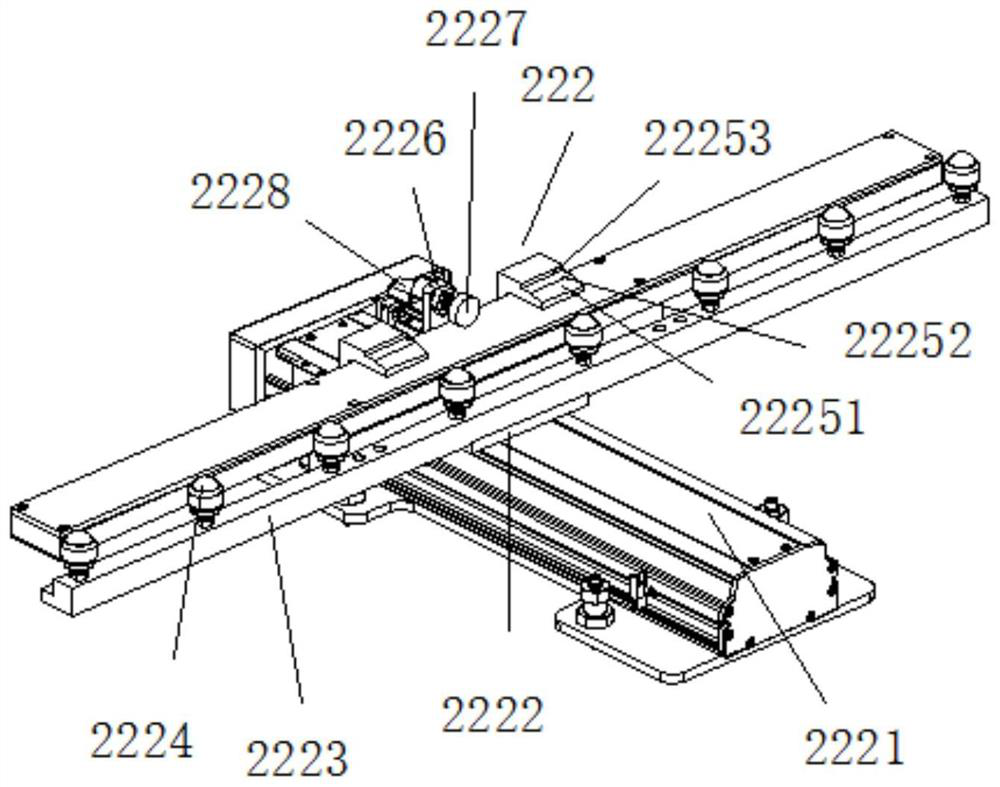
The invention discloses a deviation rectifying welding machine for a battery assembly. The deviation rectifying welding machine for the battery assembly comprises a feeding temporary storage conveyingbelt, a deviation rectifying welding line body and a discharging conveying belt which are sequentially arranged in a butt joint manner, and the deviation rectifying welding line body comprises a conveying belt, a tidying device, a visual positioning device, a deviation rectifying device, welding flow rod feeding devices and a welding device. A solar photovoltaic module is conveyed on the conveying belt, a battery string is arranged on glass, the tidying device is installed at the periphery of the conveying belt, the visual positioning device and the deviation rectifying device are arranged above the conveying belt, the welding flow rod feeding devices are arranged at the two sides of the conveying belt in a butt joint manner, and the welding device is installed on the conveying belt. By means of the manner, the battery assembly can be elastically tidied, horizontal deviation rectification can be conducted on products, and interference between every two adjacent sets of products is avoided; and a scaling powder sprayer is matched with a lead screw for spraying, the spraying requirements of different starting points are met, a welding rod can be stably connected, tight contact between a welding head and a welding point is guaranteed, and products are not damaged.

Description

technical field [0001] The invention relates to the technical field of solar module production, in particular to a deviation correction welding machine for battery modules. Background technique [0002] During the production process of solar modules, two groups of cells need to be welded together, each group includes six strings of cells, and three kinds of welding flow bars are needed to weld these cells together, and the cells are transported to the welding place through the conveyor belt, The position of the cells will be shifted during placement and transportation, the distance between the same group of cells, the distance between two groups of cells, the horizontal level of a single cell, etc., will affect the welded product. The relevant deviation correction equipment has a complex structure, and only three motors can drive the movement and rotation in the X and Y directions separately. The distance will also change accordingly, and the cost of redesigning the equipme...

Claims


Application Information

Patent Timeline
IPC IPC(8): B23P23/06B23K37/02B23K37/04B23K37/00B23K101/36
CPCB23P23/06B23K37/0252B23K37/0435B23K37/0461B23K37/00B23K2101/36
Inventor 黄曰龙贺红峰杨晨钟少华
Owner SUZHOU SHENGCHENG SOLAR EQUIP
Learn More