Centrifugal air compressor system for large-scale air separation

An air compressor and air separation technology, applied in the field of air compressors, can solve the problems of practicality and long repair time, and achieve the effects of considerable benefits, reduced energy consumption, and considerable economic benefits.

Inactive Publication Date: 2020-11-17
RIZHAO STEEL HLDG GROUP
View PDF5 Cites 1 Cited by
  • Summary
  • Abstract
  • Description
  • Claims
  • Application Information

AI Technical Summary

Problems solved by technology

[0003] In order to reduce energy consumption, a large-scale centrifugal air compressor for air separation was proposed, but the layout technology of the large-scale centrifugal air compressor system for air separation is not yet mature, and once a fault occurs, it will take a long time to repair, resulting in large-scale centrifugal air compressor system for air separation. practicality

Method used


Image

  • Centrifugal air compressor system for large-scale air separation
  • Centrifugal air compressor system for large-scale air separation
  • Centrifugal air compressor system for large-scale air separation

Examples


Embodiment 1

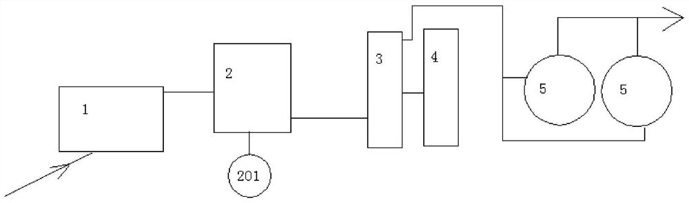
[0029] Please refer to figure 1 , the present embodiment provides a large centrifugal air compressor system for air separation, including:

[0030] Self-cleaning filter, the input end of the self-cleaning filter 1 is connected to the air inlet, the output end of the self-cleaning filter 1 is connected to the centrifugal air compressor 2 , and the centrifugal air compressor 2 is electrically connected to the motor 201 . The centrifugal air compressor 2 is connected to the air cooling tower 3; the air cooling tower 3 is respectively connected to the water cooling tower 4 and the molecular sieve 5; the molecular sieve 5 is connected to the air outlet.

[0031] The large-scale centrifugal air compressor system for air separation provided in this embodiment uses a large-scale centrifuge for air separation to transform the air supply, and its general air supply capacity is 2000-3000Nm3 / min, which is basically 10% of the air supply capacity of existing small air compressors. times, ...

Embodiment 2

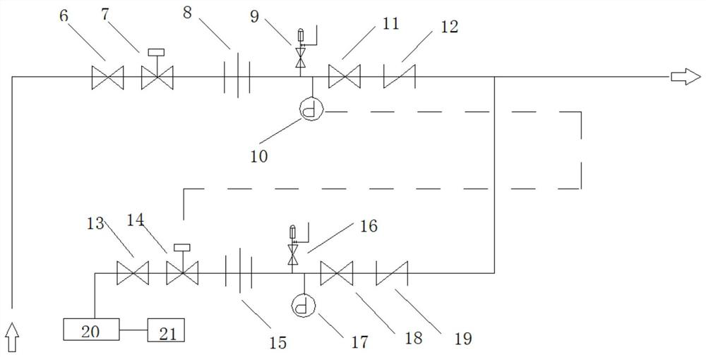
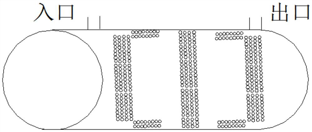
[0033] Please refer to figure 1 , figure 2 and image 3 , the present embodiment provides a large centrifugal air compressor system for air separation, including:

[0034] Self-cleaning filter, the input end of the self-cleaning filter 1 is connected to the air inlet, the output end of the self-cleaning filter 1 is connected to the centrifugal air compressor 2 , and the centrifugal air compressor 2 is electrically connected to the motor 201 . The centrifugal air compressor 2 is connected to the air cooling tower 3; the air cooling tower 3 is respectively connected to the water cooling tower 4 and the molecular sieve 5; the molecular sieve 5 is connected to the air outlet.

[0035] Among them, there are multiple molecular sieves 5, all of which are connected to the air cooling tower 3, and the desiccant in each molecular sieve 5 is filled with a grid interval structure. The small air compressor is equipped with a domestic inner-filled aluminum oxide dryer, with a flow capac...


PUM


Abstract

The invention provides a centrifugal air compressor system for large-scale air separation. The system comprises a self-cleaning filter. The input end of the self-cleaning filter is communicated with an air inlet, and the output end of the self-cleaning filter is communicated with a centrifugal air compressor. The centrifugal air compressor is communicated with an air cooling tower. The air coolingtower is respectively communicated with a water cooling tower and a molecular sieve. The molecular sieve is communicated with an air outlet. According to the centrifugal air compressor system for thelarge-scale air separation, after a series of improvements such as equipment upsizing, an automatic emergency production protection system, a resistance-free drying system and the like, the economicbenefit is considerable, and the production is not influenced under special conditions. Zero emission is achieved by reducing technological process resistance, recycling waste nitrogen or recycling; the purposes of energy conservation and emission reduction are achieved by arranging an automatic yield-keeping emergency system; and the benefit is considerable.

Description

technical field [0001] The invention belongs to the technical field of air compressors, and in particular relates to a large centrifugal air compressor system for air separation. Background technique [0002] According to statistics, the annual power consumption of air compressors in my country accounts for about 9% of the total power generation in the society, especially the air compressors in the iron and steel industry account for as much as 19%. Within 300Nm3 / min, the unit power consumption is generally 0.13kWh / Nm3, which consumes a lot of energy. [0003] In order to reduce energy consumption, a large-scale centrifugal air compressor for air separation was proposed, but the layout technology of the large-scale centrifugal air The practicality is revealed. Contents of the invention [0004] Aiming at the above-mentioned shortcomings of the prior art, the present invention provides a large centrifugal air compressor system for air separation to solve the above-mentione...

Claims


Application Information

Patent Timeline
Patent Type & Authority Applications(China)
IPC IPC(8): F25J3/04F04D29/70F04D29/58
CPCF04D29/582F04D29/701F25J3/04866F25J3/04781F25J3/04824F25J2210/04F25J2230/40F25J2230/42F25J2245/42
Inventor 高古忠
Owner RIZHAO STEEL HLDG GROUP
Why Eureka
Try Eureka