
Inter-satellite asymmetric time difference and frequency difference measurement system based on laser transparent forwarding

A time difference and frequency difference, laser transparent technology, used in radio wave measurement systems, frequency measurement devices, measurement devices and other directions, can solve the problems of large scale of equipment, large scale of antennas, affecting the measurement accuracy of time difference and frequency difference parameters, etc. The effect of measuring accuracy, improving accuracy, and reducing the scale of system equipment

Active Publication Date: 2020-11-17
SHANGHAI SATELLITE ENG INST
View PDF4 Cites 2 Cited by
  • Summary
  • Abstract
  • Description
  • Claims
  • Application Information

AI Technical Summary

Problems solved by technology

[0003] The patent document CN105759241A invention patent discloses a direct positioning method of time difference and frequency difference. Aiming at the problem of double satellite time difference and frequency difference positioning, a method of first solving TOA and then performing direct positioning based on FDOA information is provided. The difference from this patent is that : (1) Multi-channel signals need to be frequency converted, amplified, and sampled separately, and the scale of equipment is large; (2) Multi-channel signals are not sampled and processed under the same time-frequency reference by laser transparent forwarding, and multiple satellite platforms are introduced The inherent time-frequency error between the satellites affects the measurement accuracy of the time difference and frequency difference parameters; (3) multi-channel signals need to complete the signal sampling and parameter measurement respectively, and the receiving sensitivity requirements of each satellite are the same, and each satellite needs to use the same scale receiving antenna. big

Method used


Image

  • Inter-satellite asymmetric time difference and frequency difference measurement system based on laser transparent forwarding
  • Inter-satellite asymmetric time difference and frequency difference measurement system based on laser transparent forwarding
  • Inter-satellite asymmetric time difference and frequency difference measurement system based on laser transparent forwarding

Examples


Embodiment Construction

[0033] The present invention will be described in detail below in conjunction with specific embodiments. The following examples will help those skilled in the art to further understand the present invention, but do not limit the present invention in any form. It should be noted that those skilled in the art can make several changes and improvements without departing from the concept of the present invention. These all belong to the protection scope of the present invention.

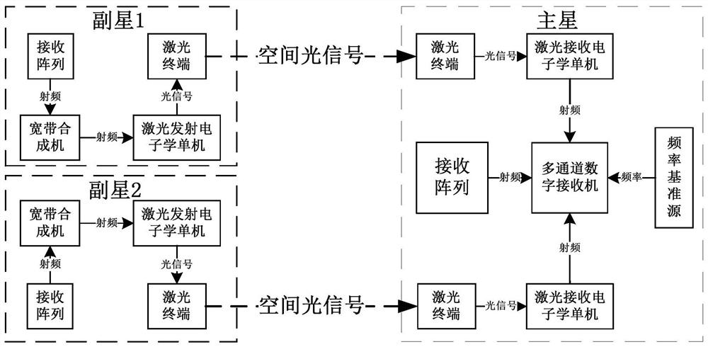
[0034] Such as figure 1 As shown, this embodiment provides an inter-satellite asymmetric time difference and frequency difference measurement system based on laser transparent forwarding, which is described with a typical three-star system. Adopt broadband microwave signal laser transparent forwarding design: the two sub-stars modulate the received broadband microwave signal onto the optical carrier, transmit it through the laser terminal of the sub-star, and transmit the optical signal to the laser ter...


PUM


Abstract

The invention provides an inter-satellite asymmetric time difference and frequency difference measurement system based on laser transparent forwarding, which comprises a primary satellite device and aplurality of secondary satellite devices. A plurality of secondary satellite devices modulate received broadband microwave signals onto an optical carrier and transmit the signals through laser terminals of secondary satellites; then the optical signal is transfered to a laser terminal of the main satellite through a free space channel to finish receiving, and photoelectric conversion on the mainsatellite is completed to restore the broadband microwave signal. By means of the system, difference and frequency difference measurement of a multi-satellite system can be achieved. The system is high in time difference and frequency difference measurement precision, small in system scale, high in system receiving sensitivity and the like; when the system is applied to radiation source passive positioning, the positioning precision can be improved, the system cost can be reduced, and great reference significance is achieved in the field of satellite-borne passive positioning.

Description

technical field [0001] The invention relates to the field of satellite-borne passive positioning technology, in particular to an asymmetric inter-satellite time difference and frequency difference measurement system based on laser transparent forwarding. Background technique [0002] Passive positioning technology is widely used in aviation, aerospace, measurement and control and other fields due to its high positioning accuracy, wide range of action, high concealment, and strong environmental adaptability. When there are multiple satellites, due to the different positions of the satellites, the distance between the target and the two satellites is different, and the time for the signal from the radiation source to reach the satellite is different, forming time difference information (Time Difference of Arrival, TDOA), and the high-speed motion of the satellite Compared with the radiation source, the Doppler effect is generated, and the signal frequency received by the satel...

Claims


Application Information

Patent Timeline
Patent Type & Authority Applications(China)
IPC IPC(8): G01R23/02G01S5/02
CPCG01R23/02G01S5/0268Y02D30/70
Inventor 王瀚霆陈占胜成飞陈锋曲耀斌宋玉亭陶满意代海山
Owner SHANGHAI SATELLITE ENG INST
Learn More